Providing the Right Level of M&E Details
The level of M&E details required varies depending on the project typology. Close coordination across disciplines – particularly among the Architect, C&S Engineer, and M&E Engineer – is important. A development’s functionality depends on a wide range of services, ranging from sewerage and sanitary routing to ventilation. Therefore, M&E services are an important aspect that should not be overlooked, even as the building form is being finalised.
Typical modelling method for MEP systems in compliance with IFC+SG requirements
While it may seem ideal to provide all the information, overly detailed models can lead to system performance issues and longer processing times. Therefore, it is important to strike a balance between the level of information available and the optimal level to be provided. To do this effectively, project teams must understand the rationales behind each regulatory requirement and provide only the relevant details needed to support regulatory compliance.
Modelling Regulated M&E Aspects
M&E components that are directly regulated must be included in the submission and modelled, as per the CORENET X COP Examples of such requirements include:
Drainage Aspects, Public Utilities Board (PUB)
Sewerage and Sanitary, PUB
Exhaust for carpark, toilets and kitchens, National Environment Agency (NEA)
As models will take time to export to IFC+SG format, particularly for larger development projects, which can delay the submission process, to manage this, project teams could continue coordinating in their native BIM environment, only exporting the necessary elements for regulatory submission to IFC+SG.
Managing M&E BIM Models of the M&E services
It is not necessary to bind all the M&E services in separate BIM models into one large BIM file. Effective coordination with fellow disciplines by federation of BIM models in all BIM authoring software and viewers. Typically, different M&E services are modelled in separate files for effective management of each service. If the team prefers to combine multiple M&E services in one BIM file, QPs should assess whether the model size remains manageable and whether it is sustainable for subsequent collaboration with other disciplines and version control.
Modelling of systems
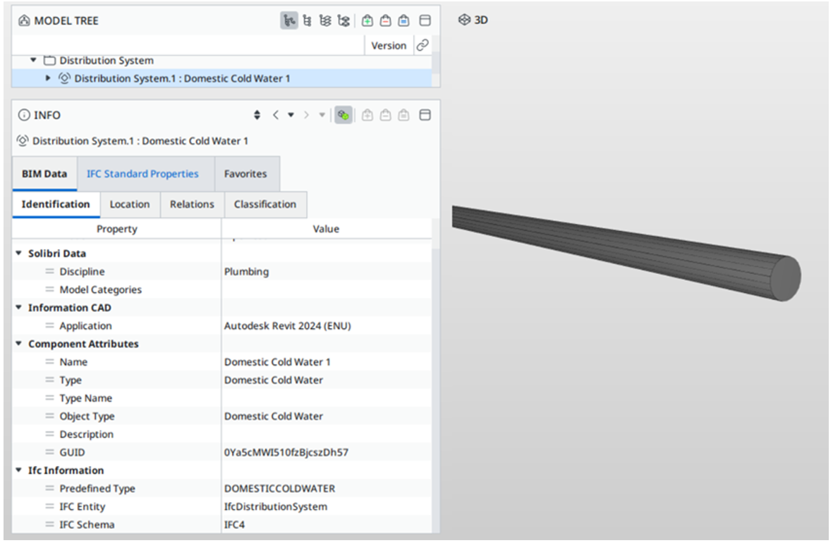
As part of the efforts to streamline modelling requirements, elements in the M&E system in the BIM models are now identified via its system classification and system name based on the two key parameters “SystemType” and “SystemName” which are readily available in the BIM authoring software and commonly used by the industry.
Examples of “SystemType” are “Drainage”, “Sanitary”, “Sewerage”, “Potable Water”, “Sprinkler”, “Wet Riser”. For ACMV system, the “SystemType” should typically follow the format – “{spacename} / {equipment} + Fresh Air/ Exhaust Air”
“SystemName” is the unique name given to each system based on individual project requirements.
For example,
| IFC Entity: IfcPipeSegment | ||||||
|---|---|---|---|---|---|---|
| IFC SubType: RIGIDSEGMENT, FLEXIBLESEGMENT | ||||||
| S/N | IFC+SG Property | Property Type | Type of Elements | Unit | Input Limitation | Examples |
| 1 | SystemType | Text | - | - | No | Please see List of System Types |
| 2 | SystemName | Text | - | - | No | - |
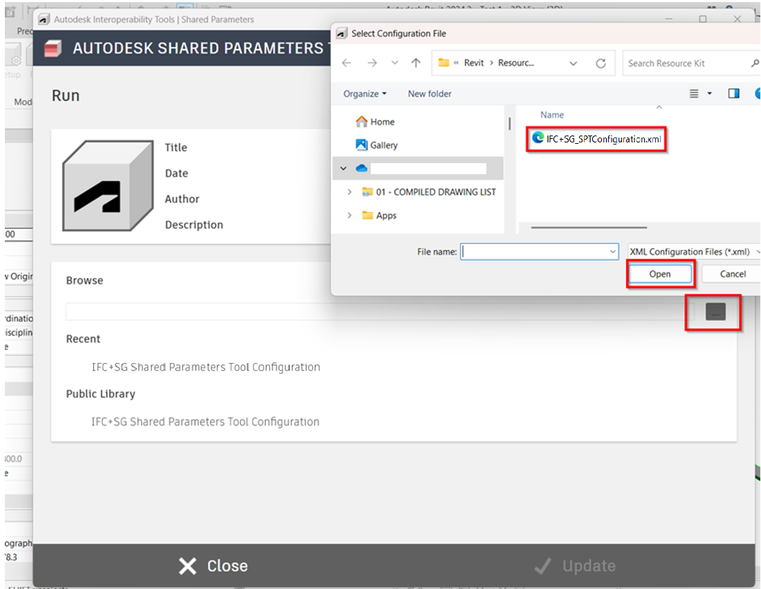
1. Using the new or current working model, load the “IFC+SG_SPTConfiguration” to update the parameters under Interoperability tab > Run. Click OK once all the parameters are updated.

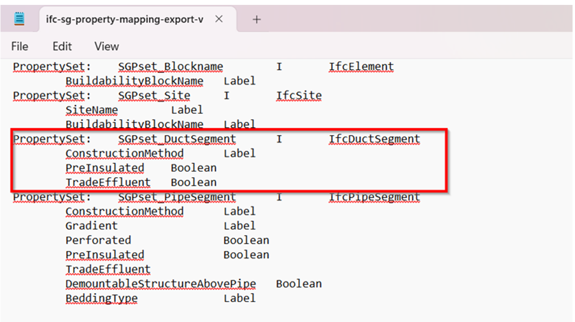
2. For duct models ensure that the required data and parameters are properly incorporated in the model based on the industry mapping template.
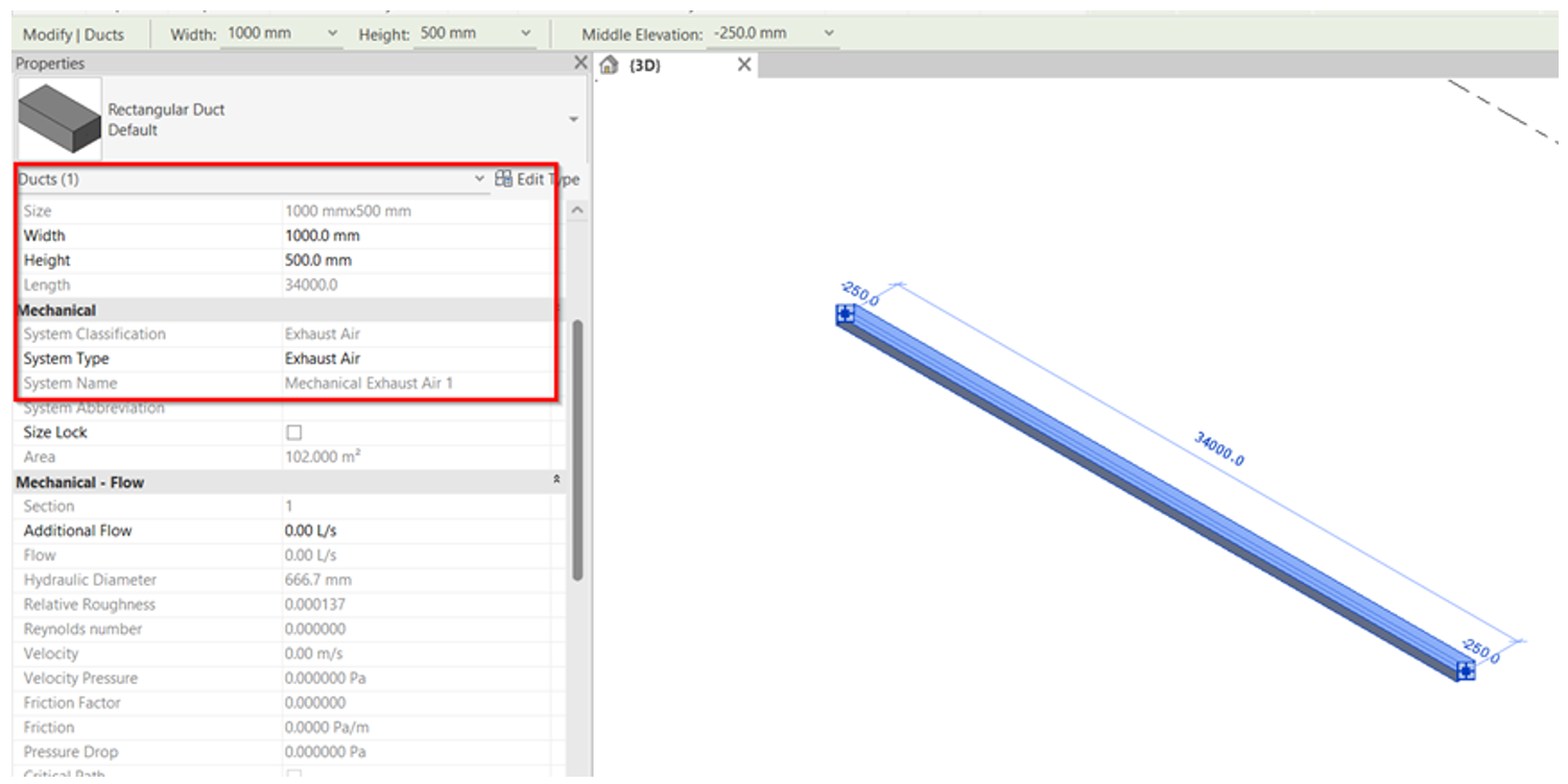
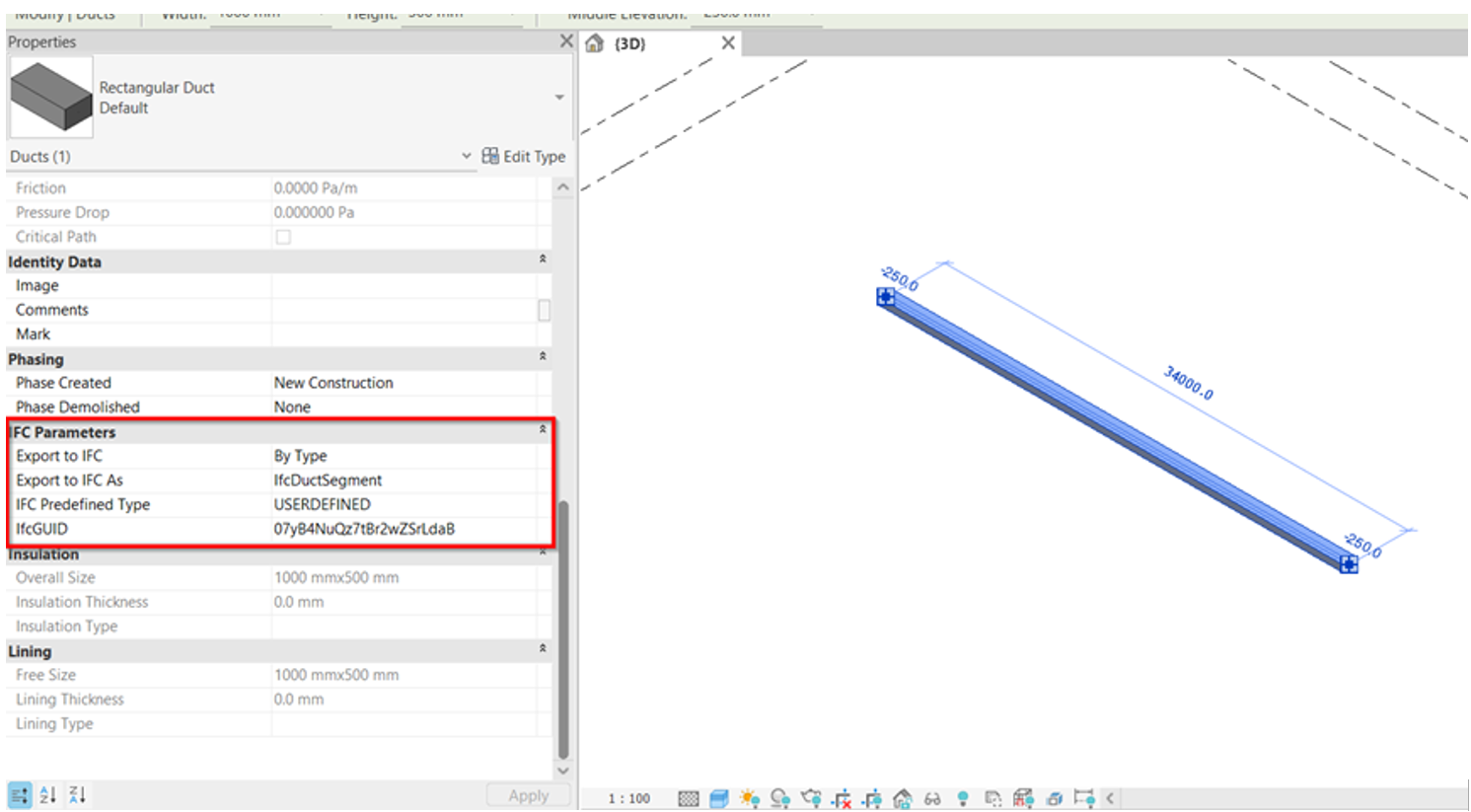
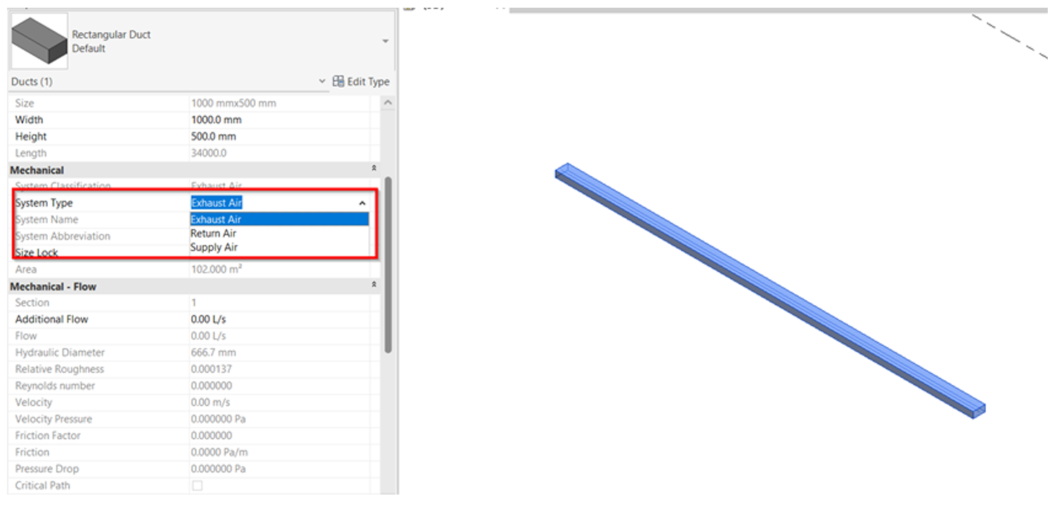
3. In reference to the system value, this will be captured automatically during IFC exports.
4. Ensure that all necessary parameters are captured based on the industry mapping template. Select what IfcElement and assign the type from the list.
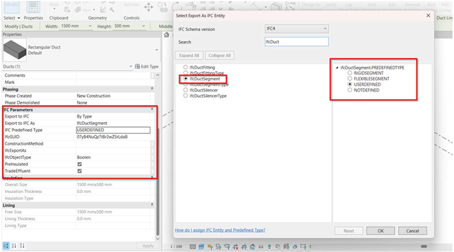
5. As per the SPT Configuration Template, there are existing parameters that complies to the industry mapping and if there’s a missing parameter that needs to be created based on the reference, the user/modeler can always add new shared parameter under Manage tab > Shared Parameters.

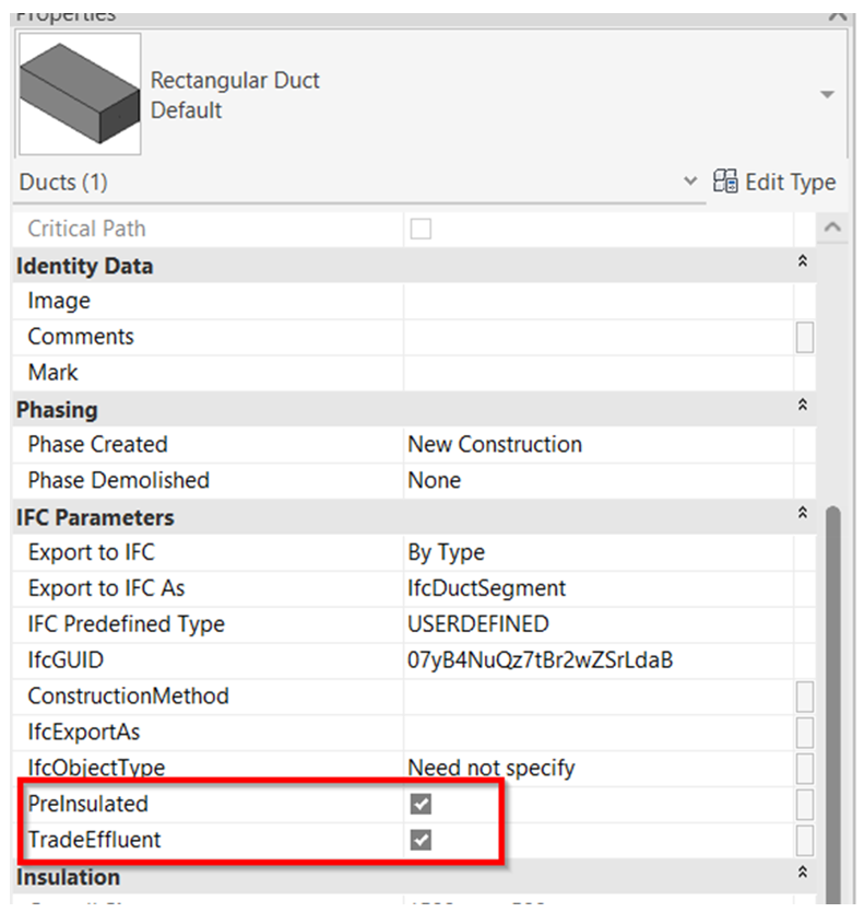
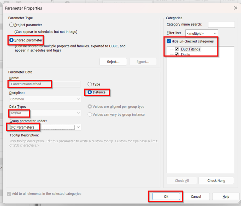
6. Once all shared parameters are created and the data were properly incorporated, can proceed to Export the model to IFC using the steps below. File > Export > IFC
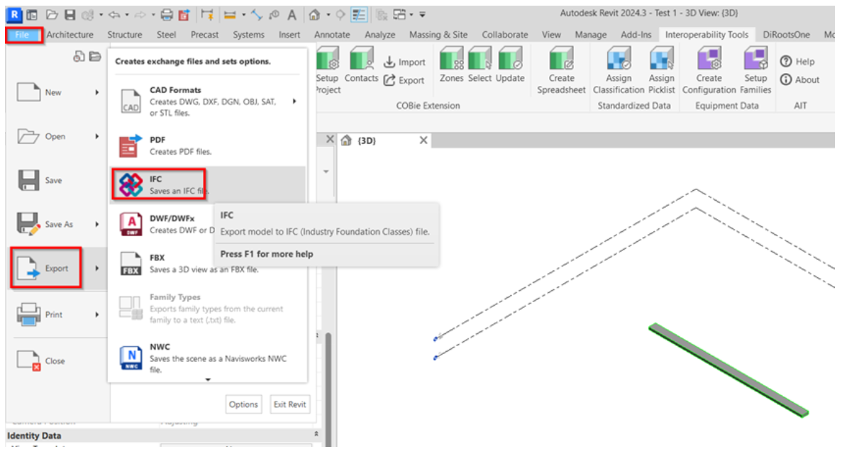
7. Additional settings before exporting.
a. Select “Modify Setup” in the export dialog box.
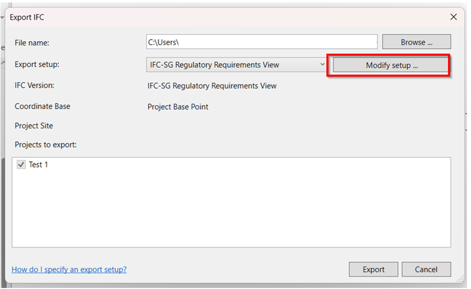
b. Duplicate the “IFC-SG Setup” to be able to adjust the other additional settings.
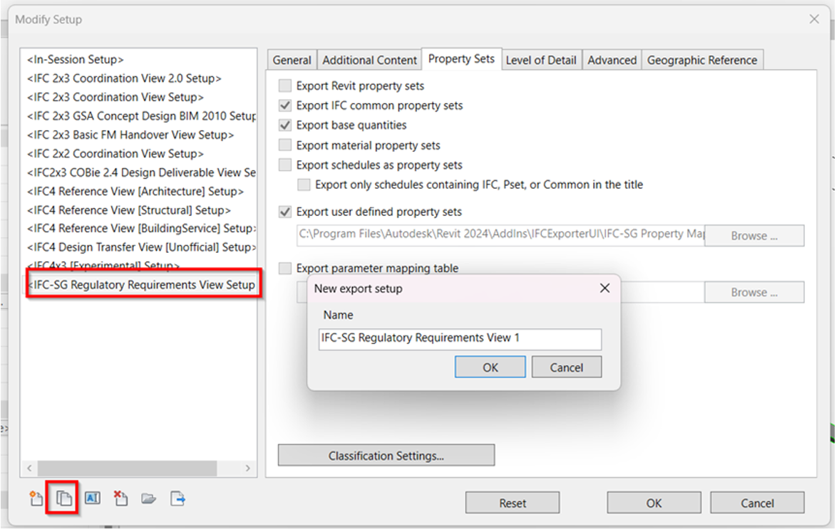
c. Under “Property Sets” tab in the Setup box, browse the mapping template and click Open.
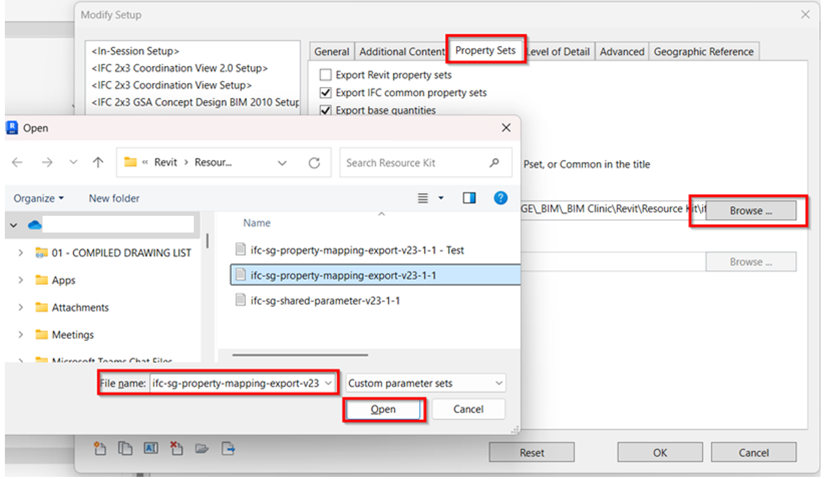
d. To Note: To ensure that the parameters are added into Industry mapping template.
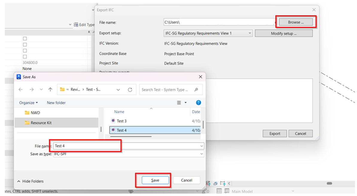
e. Browse the desired location to save the exported IFC file.
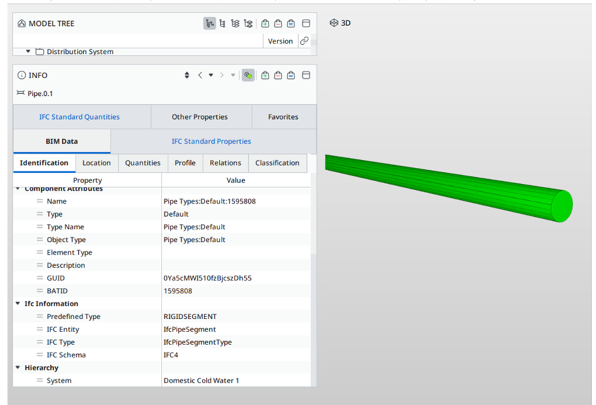
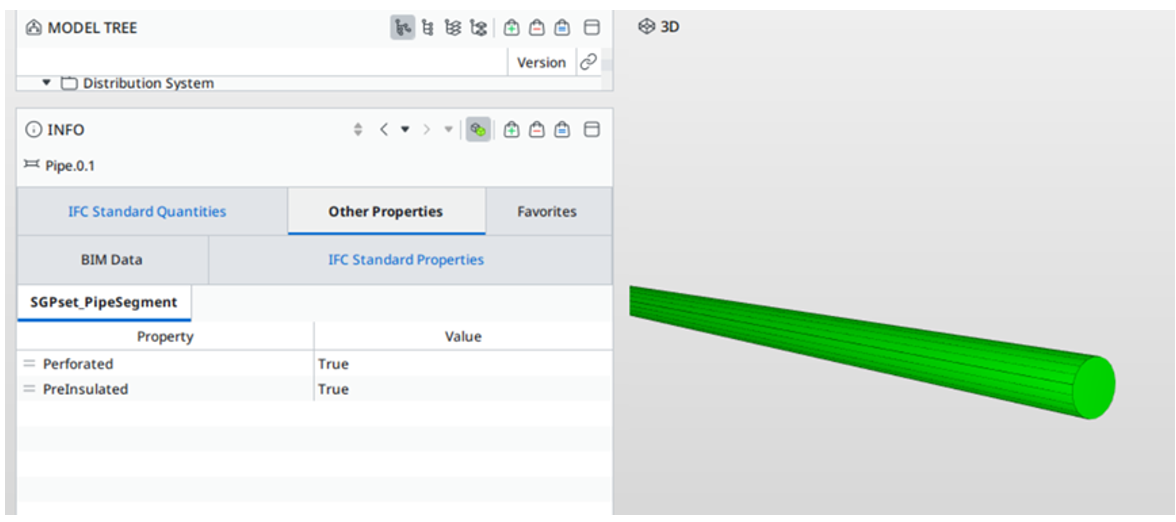
8. Verify the IFC model using any IFC viewer if all the necessary parameters as per Industry mapping template are captured.
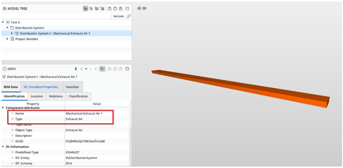
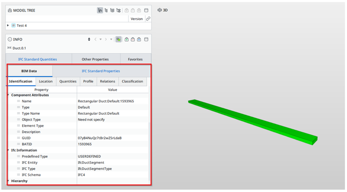
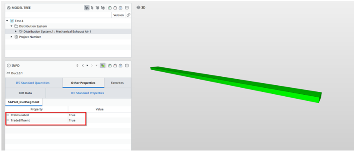
1. Using the new or current working model, load the “IFC+SG_SPTConfiguration” to update the parameters under Interoperability tab > Run. Click OK once all the parameters are updated.


2. For Pipe model ensure that the required data and parameters are properly incorporated in the model based on the industry mapping template.
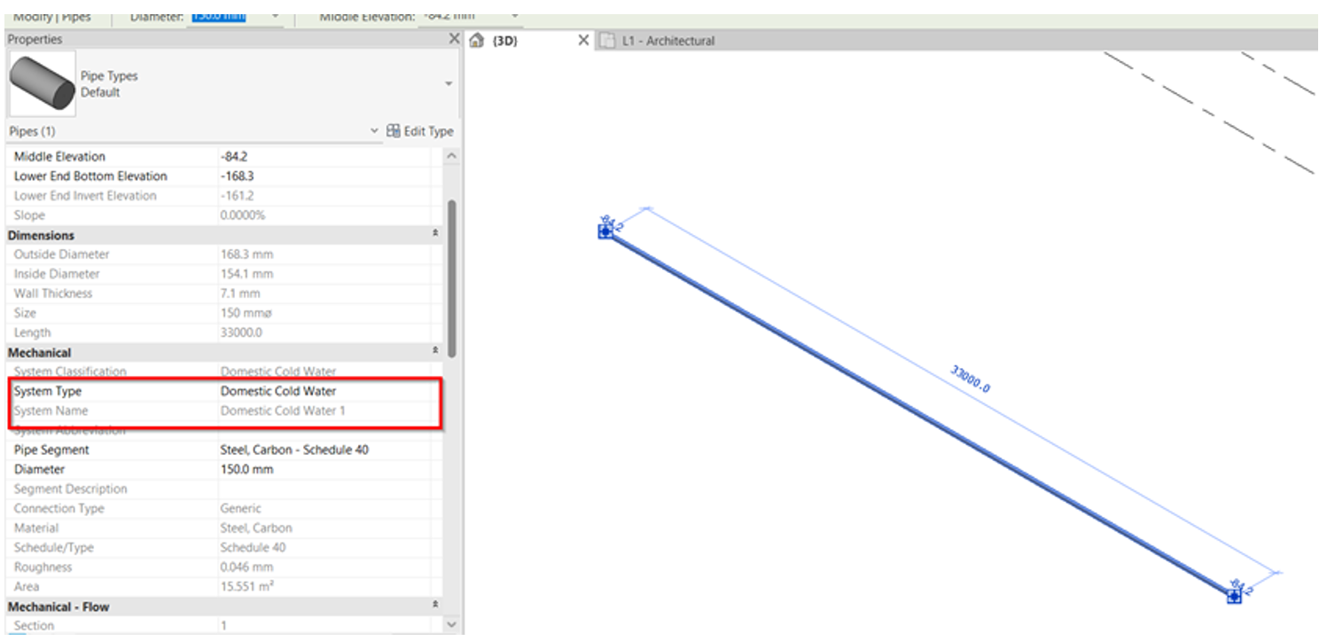
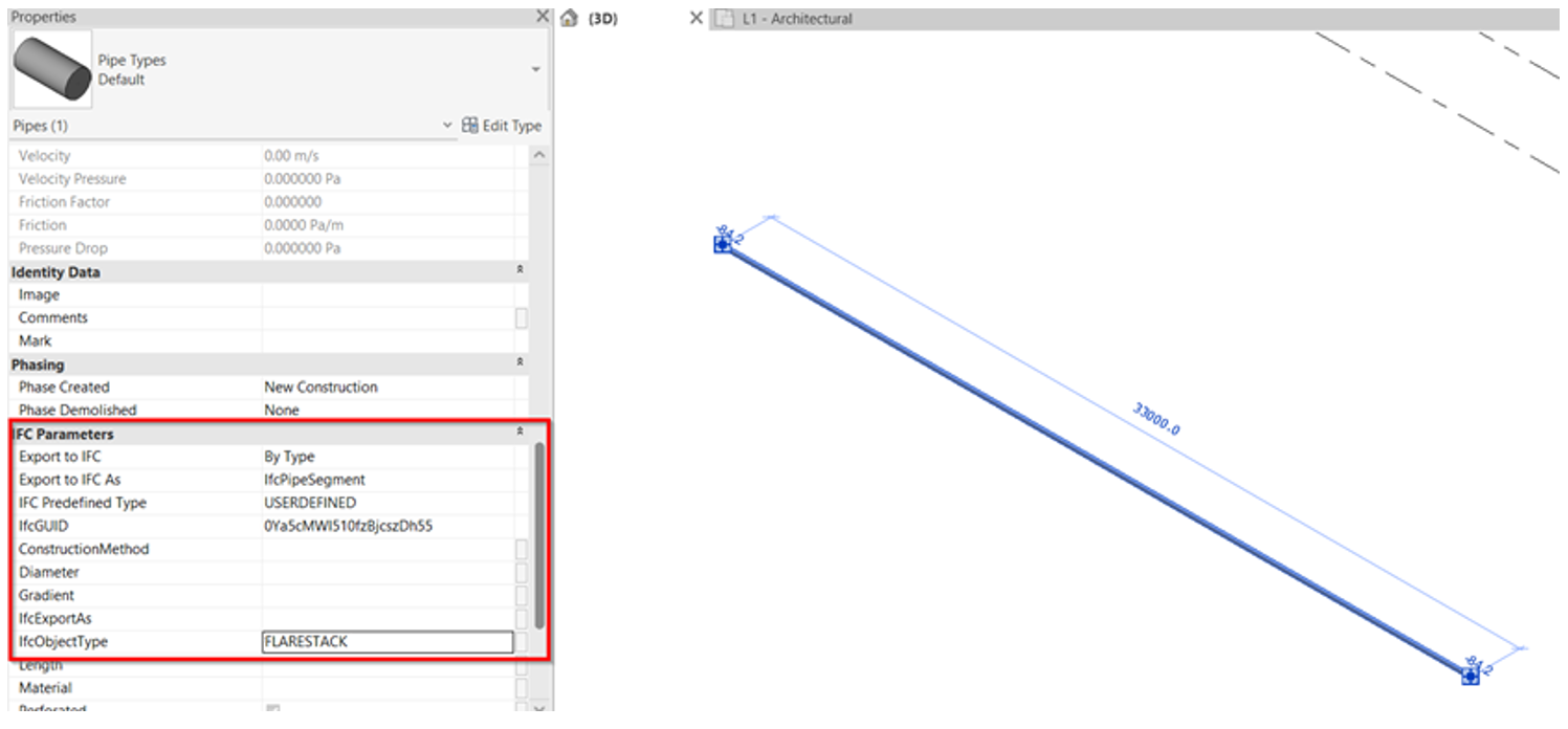
3. In reference to the system value, this will be captured automatically during IFC exports.
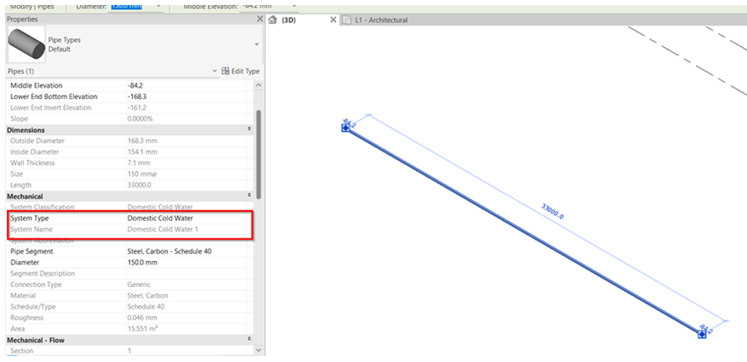
4. Ensure that all necessary parameters are captured based on the industry mapping template. Select what IfcElement and assign the type from the list.
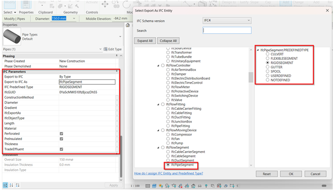
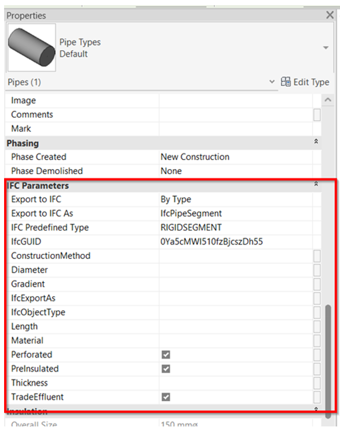
5. As per the SPT Configuration Template, there are existing parameters that complies to the industry mapping and if there’s a missing parameter that needs to be created based on the reference, the user/modeler can always add new shared parameter under Manage tab > Shared Parameters.

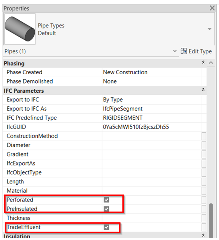
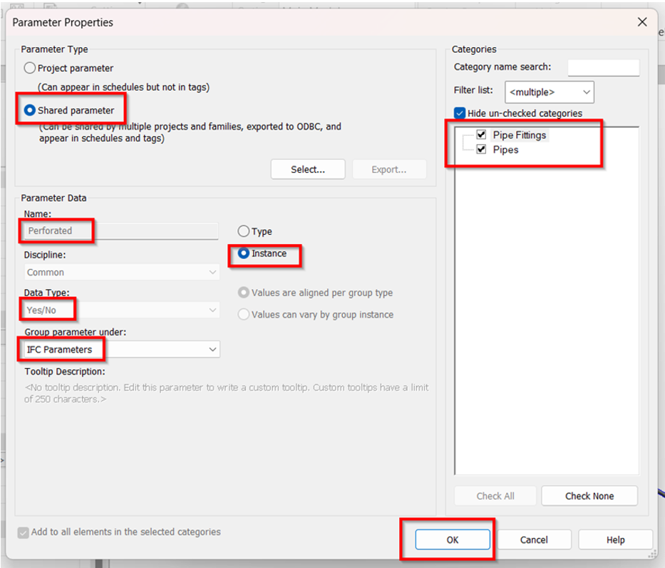
6. Once all shared parameters are created and the data were properly incorporated, can proceed to Export the model to IFC using the steps below. File > Export > IFC
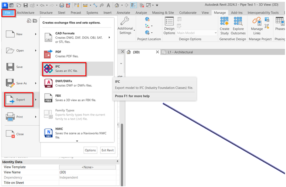
7. Additional settings before exporting.
a. Select “Modify Setup” in the export dialog box.

b. Duplicate the “IFC-SG Setup” to be able to adjust the other additional settings.

c. Under “Property Sets” tab in the Setup box, browse the mapping template and click Open.

d. To Note: To ensure that the parameters are added into Industry mapping template.
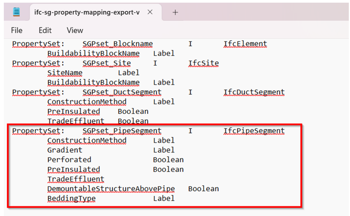
e. Browse the desired location to save the exported IFC file.

8. Verify the IFC model using any IFC viewer if all the necessary parameters as per Industry mapping template are captured.
