Geo-referencing and coordination across disciplines
These good practices provide a recommended approach on project setup to address model coordination issues across various disciplines and to facilitate effective collaboration, especially across different BIM software. We welcome feedback and suggestions from industry practitioners to help us improve and expand our good practices for industry practitioners' reference and consideration.
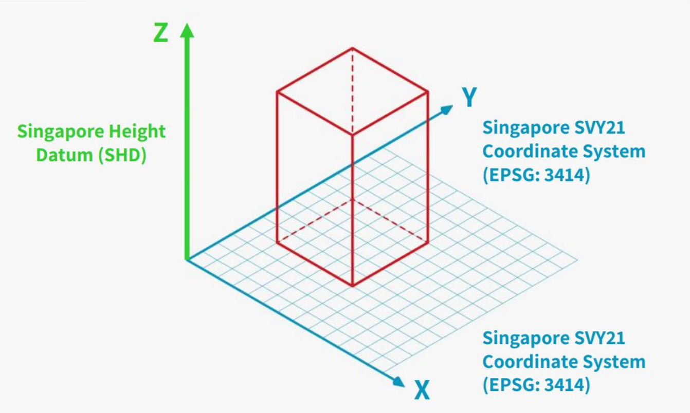
Models should be correctly geo-referenced and assigned real-world coordinates from the Singapore SVY21 coordinate system (EPSG: 3414) for Easting and Northing (x,y), including dimensions between grids. The layout of each model shall be presented in True North or real-world orientation, and the elevation levels or Height (z) of the model shall be set up based on the Singapore Height Datum (SHD).
The Singapore Institute of Surveyors and Valuers - Land Surveying Division has also come up with a video on geo-referencing, to explore how land surveyors and architects can work together to have more efficient workflow for future CORENET X submission.
Basic Geo-Referencing Checks
Advanced Troubleshooting
2. Revit and ArchiCAD Users: Graphisoft ShareFile
1. Download ArchiCAD IFC+SG Tool kit

2. Use the IFC+SG template and relevant libraries in the tool kit to create the new project.
3. Obtain the Survey Points from the surveyor.

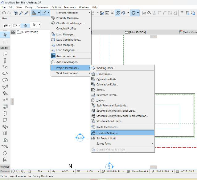
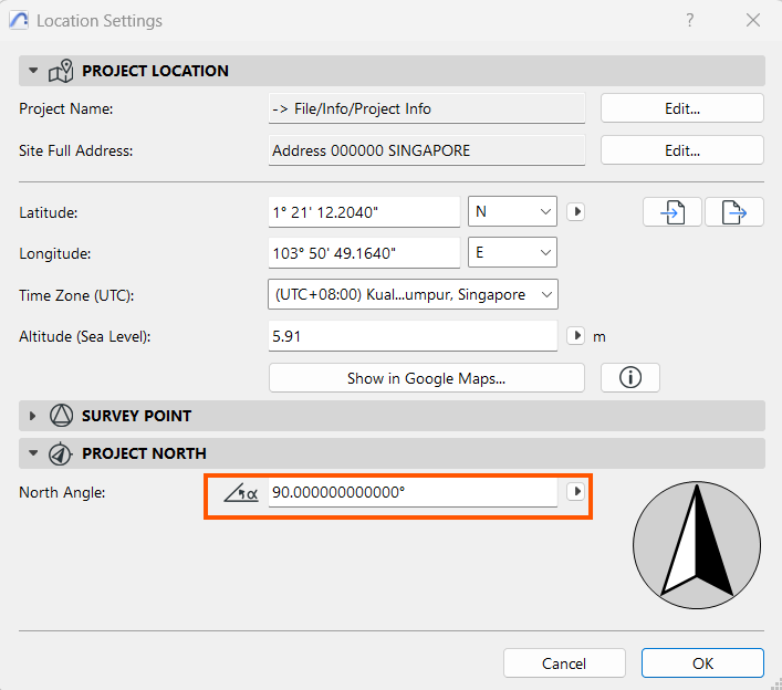
4. Set up the Position as per Survey Coordinates received from the surveyor. This can be set using Project Preferences > Location Settings
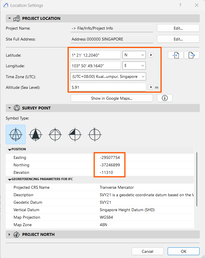
5. Key in the information from surveyor data in the dialogue box as below:
Also, key in the Project North Angle:
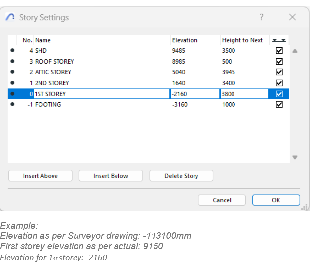
6. From the Project Map, go to the Storey Settings:

Use the dialogue box below to key in the elevation in relation with the elevation received from the Surveyor in the Storey Settings dialogue box.
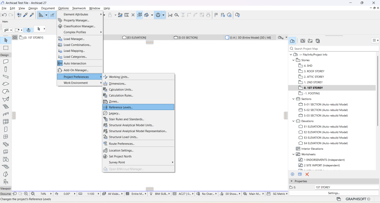
7. Set the correct elevations in Project Preferences for Reference Levels:
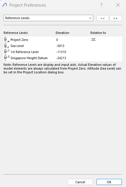
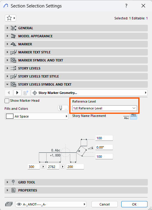
Coordinates should reflect correctly after the above settings as in the example below:
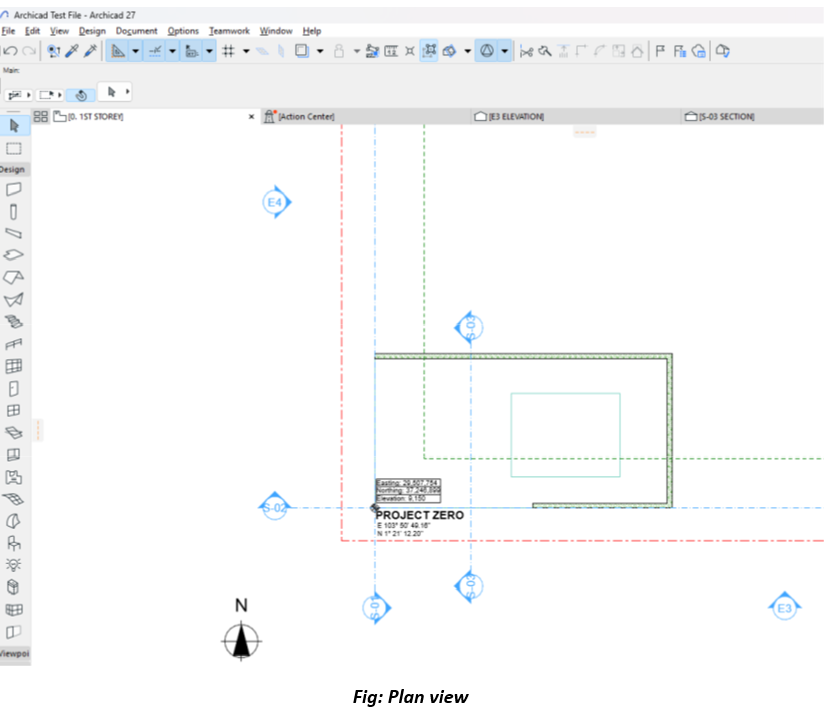
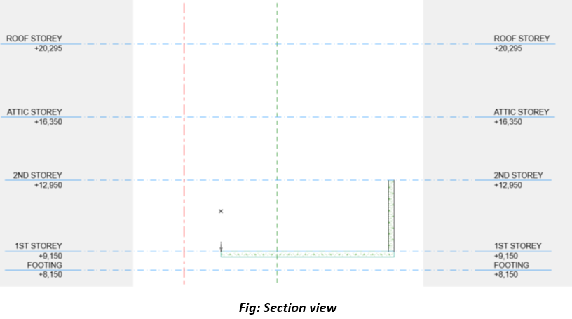
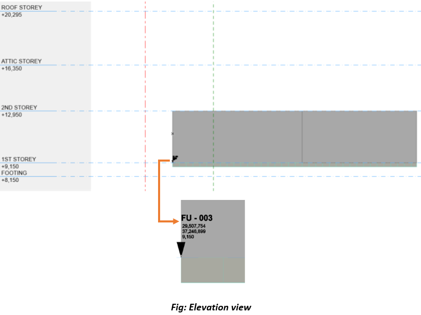
1. Obtain Survey Information:
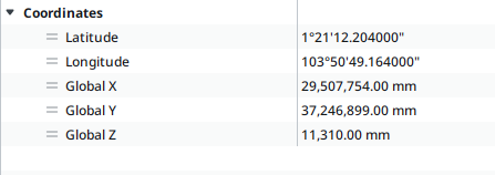
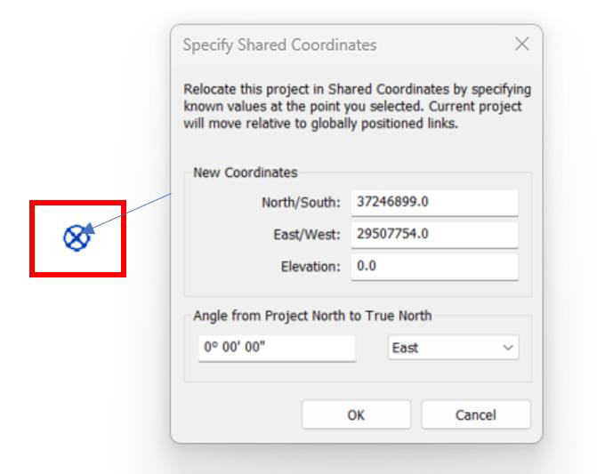
Use the Manage tab > Coordinates > Specify Coordinates at Point. And key in survey point values.
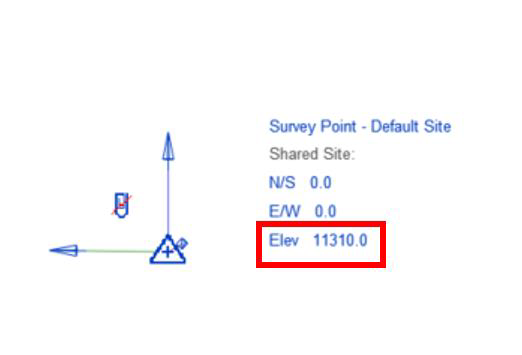
3. Set elevation at Revit Survey point: Enable the Survey Point & define elevation value.
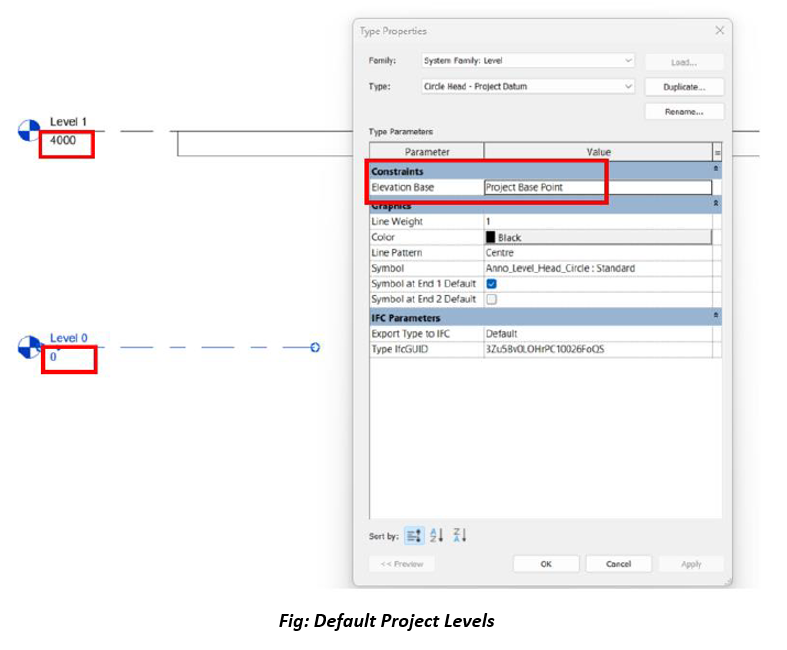
4. Define Project Level and fill elevation value and make sure elevation base is from the Project Base Point.
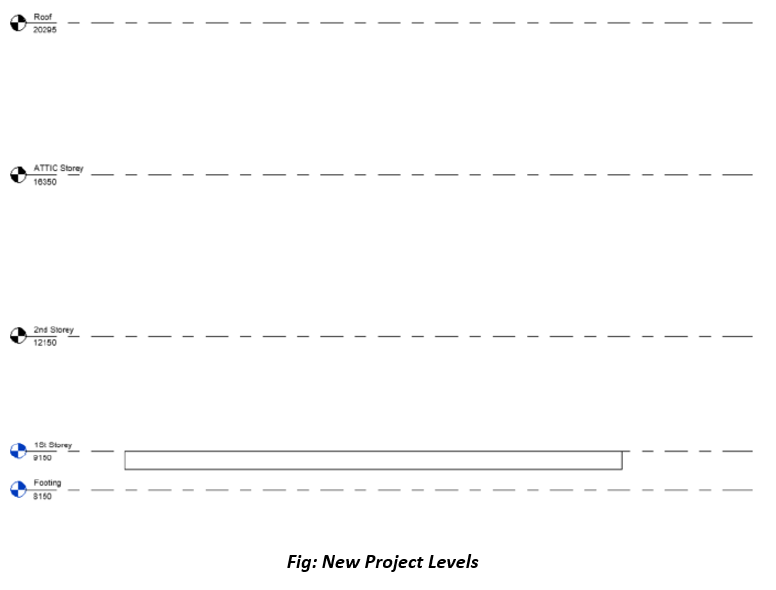
Setting Up Project Reference Point Based on Existing Revit Coordinates
1. Set Up a New Revit File:
• Create a new Revit file using the desired template.
• Go to Insert > Link Revit and link the existing Revit file that has the correct coordinates.
• Ensure to review and match naming conventions and alignment for levels and grids.
• Select the linked Revit file. This action transfers the coordinate system (Survey Point, Project Base Point, and True North) from the existing file to the new file.
• Save the new Revit file, which now has the same coordinate system as the original file.
• Ensure the export includes geographic reference set as shared Coordinates
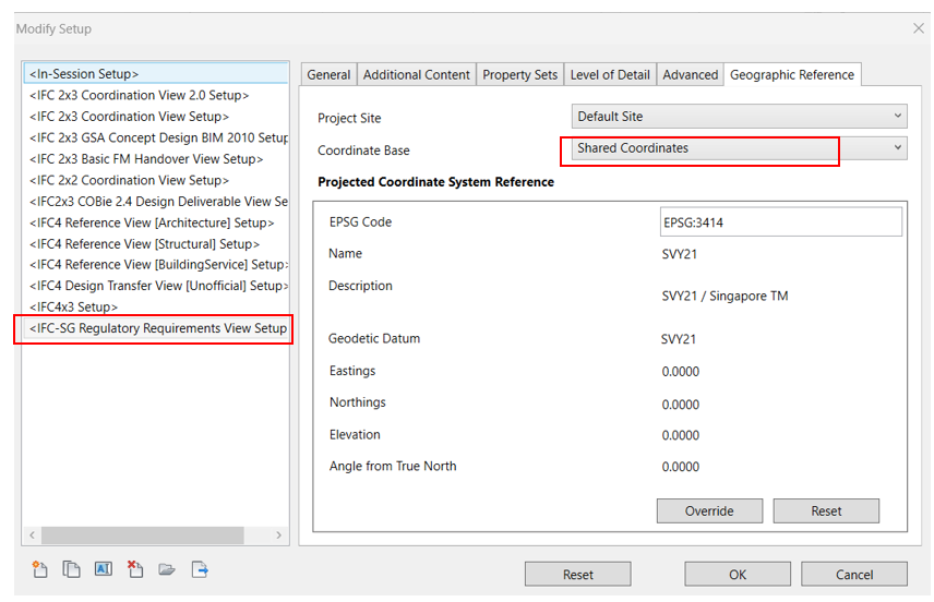
Linking IFC File Exported from ArchiCAD into Revit (If Applicable)
1. In Revit, go to Insert > Link IFC
• Select the exported IFC file and link it to the Revit project.

• Use Section and Plan views to confirm alignment.
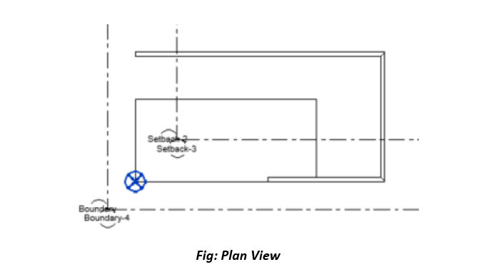
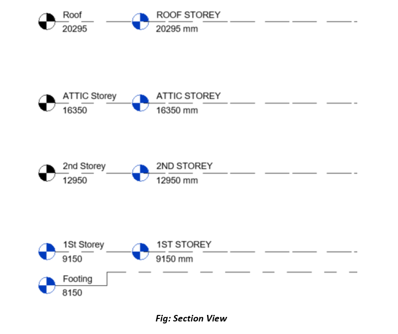
• Ensure the export includes geographic reference set as shared Coordinates

As part of the coordinated BIM model submitted by the QPs, BIM models from all disciplines MUST adopt a coordinated set of levels and zones and name the levels and zones identically. In addition, project teams can ensure better coordination by following the same set of established naming conventions for building levels.
- Only multi-disciplinary models with identical names and “Z” values for levels will be processed by Processing Officers in the CORENET X Collaboration Platform.
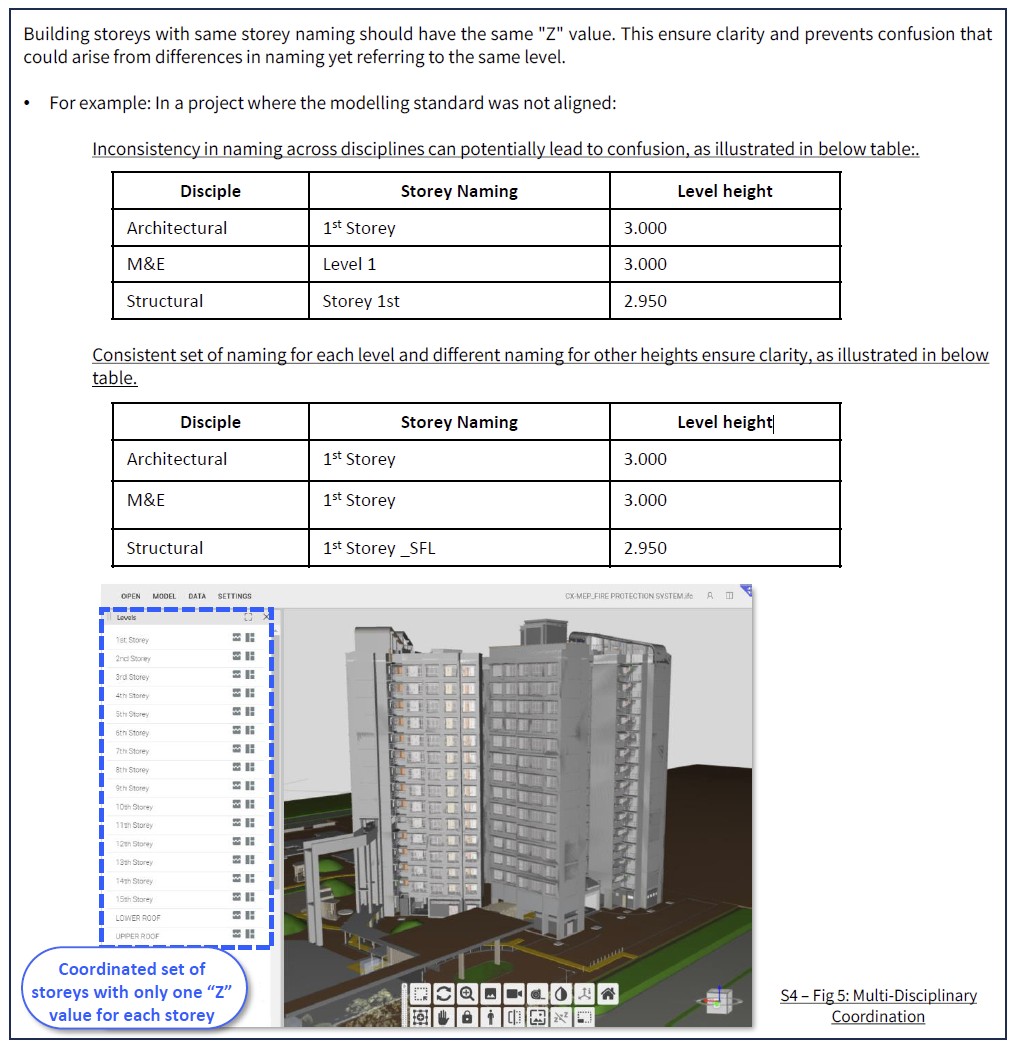
At the same time, IFC standard recommends that elements in the BIM models, including storey, retain a unique GlobalId (Globally Unique Identifier) across all models to support data integrity and accurate model referencing. Please refer to here for further guidelines on how to ensure consistency in levels and achieve unique GlobalId across all BIM models for your project.
1. Using your new project or existing project Revit interface, link the IFC model.
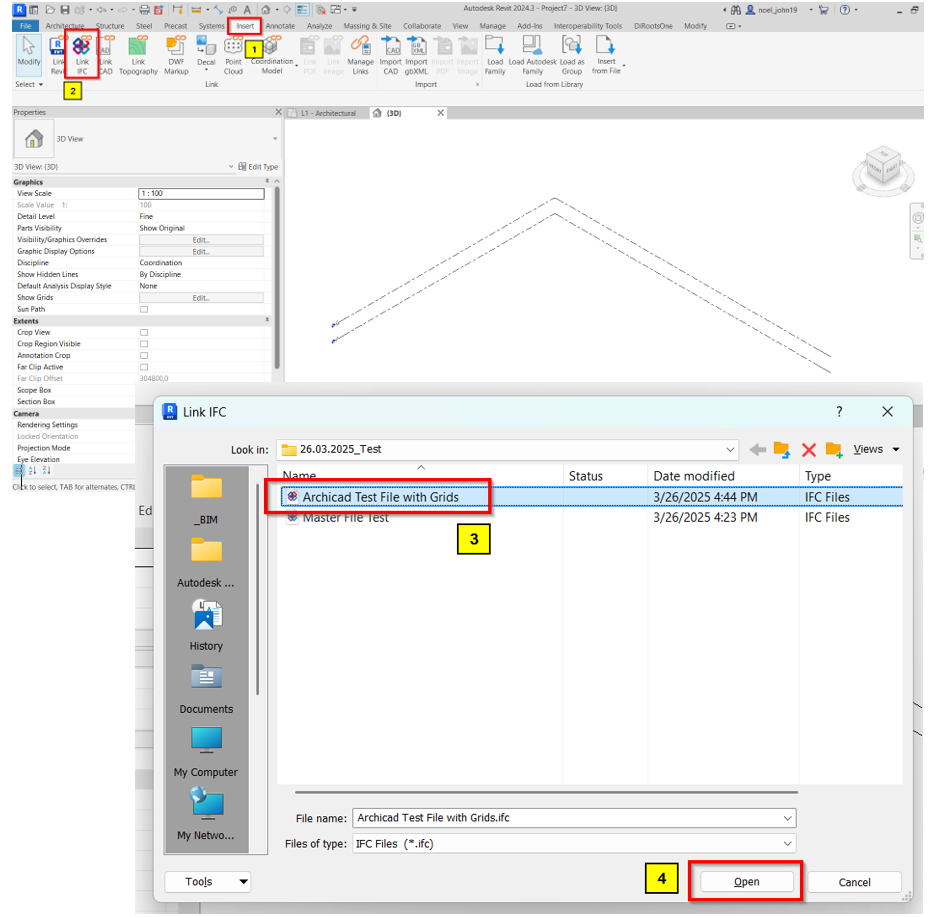
2. Once IFC model is loaded, go to Collaborate tab and look for “Copy/Monitor” tool. Pick “Select Link” and select the linked IFC model where the elements need to copy from.
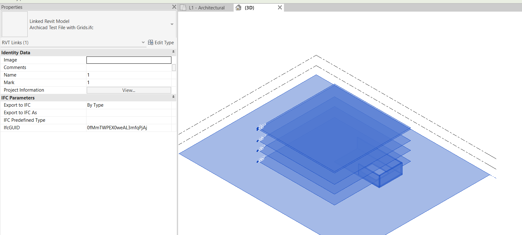
3. Once the linked IFC Model is selected, the model is now under edit mode and the user/modeler can now start copying the elements they need.
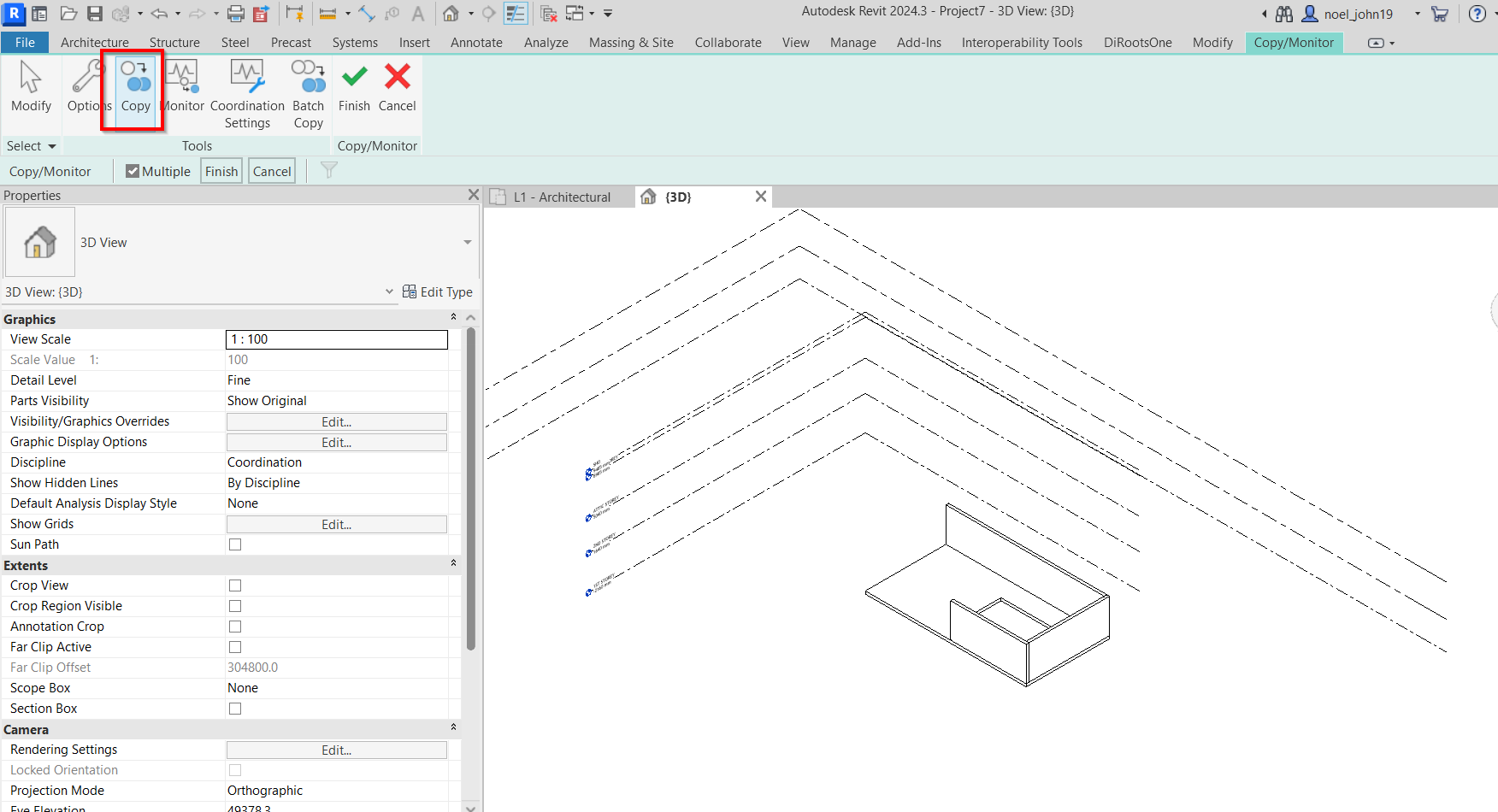
4. Uncheck “Multiple box” means copying 1 element or 1 at a time, checked “Multiple box” means selecting more than 1 elements.
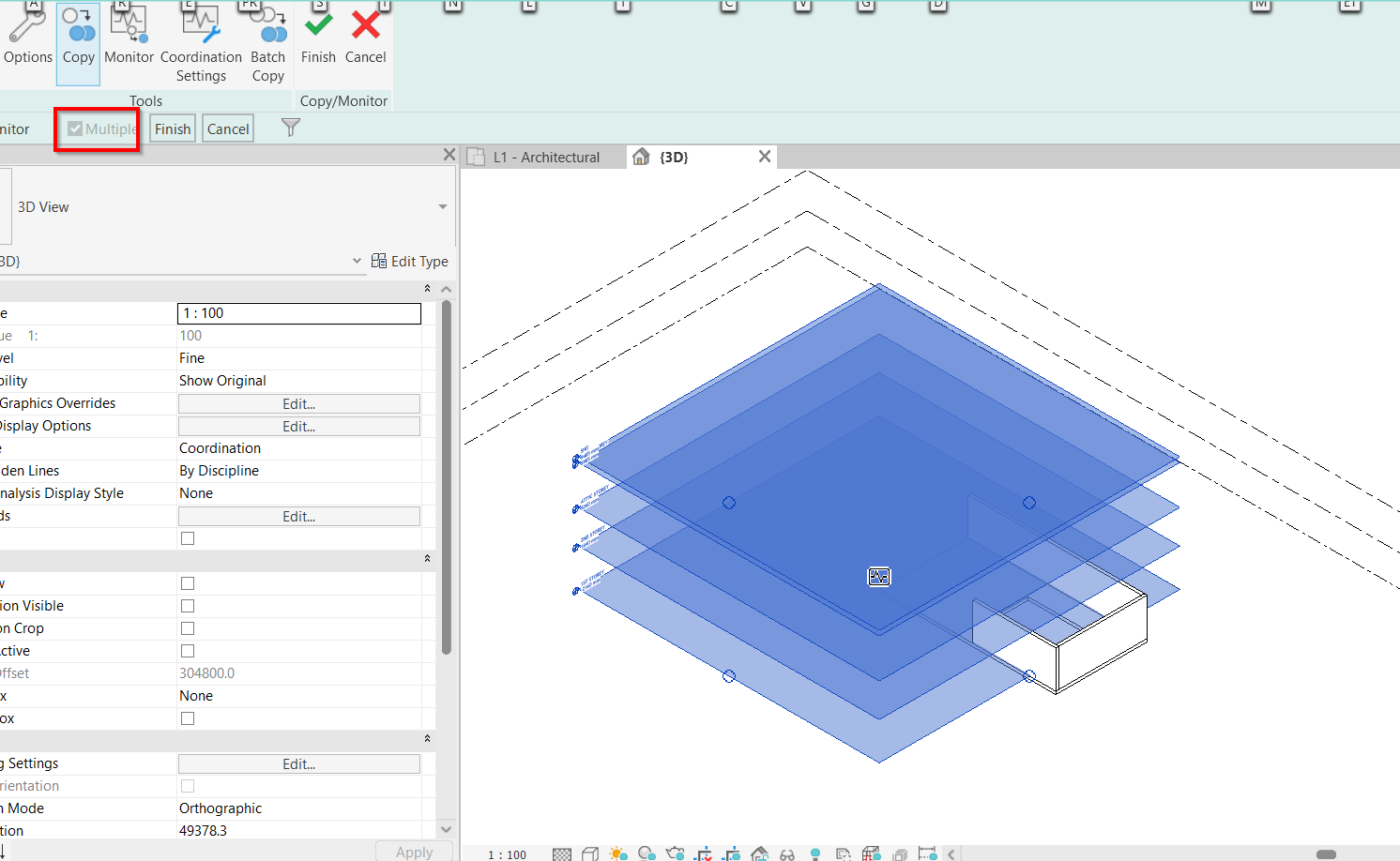
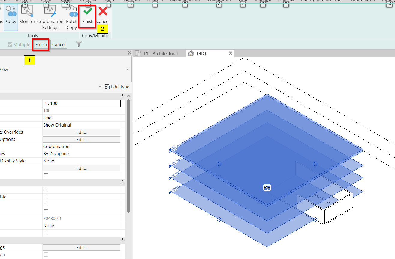
5. Once done in selection of elements, user/modeler can now click “Finish” for copying procedure and another “Finish” option for ending the edit mode.
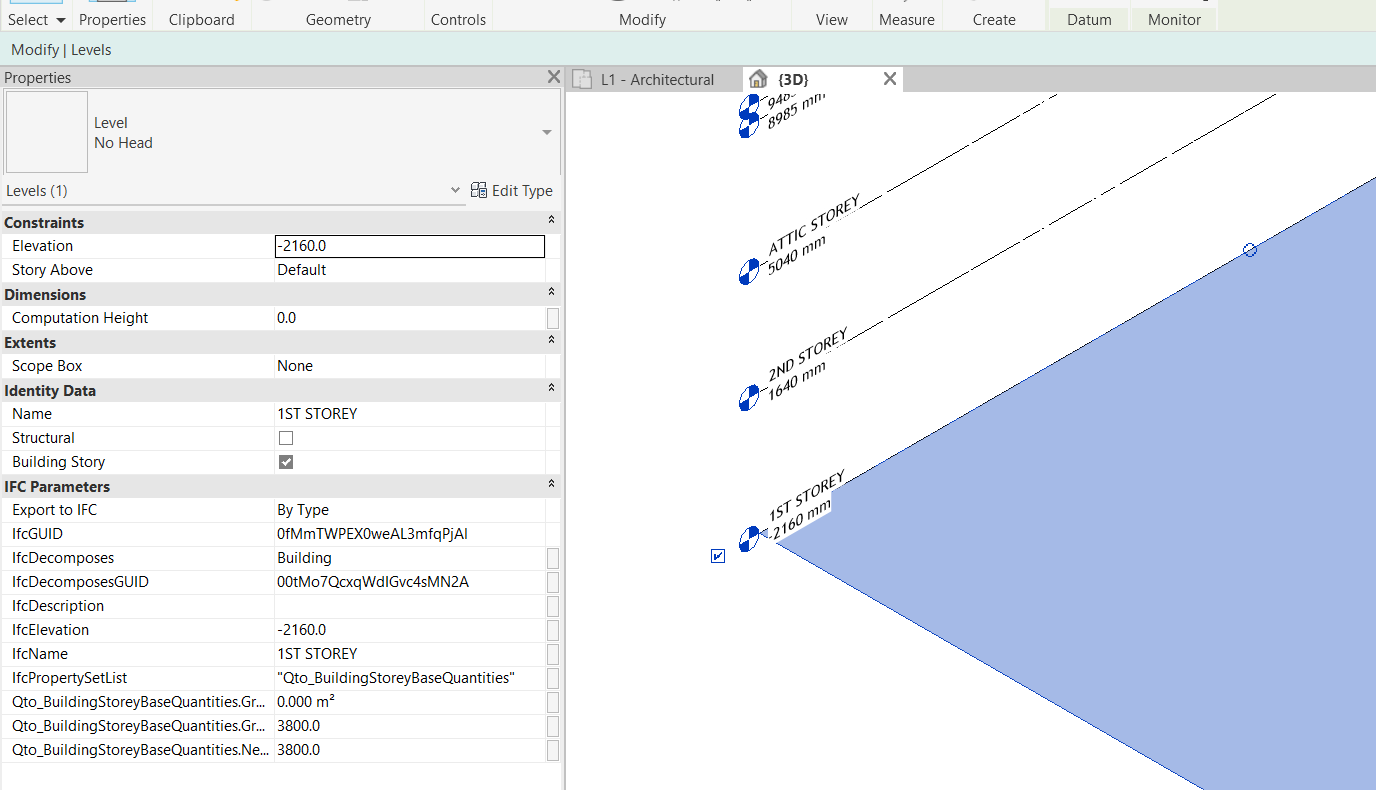
6. Verify the copied elements and it’s ifc properties.
1. One option to place the ArchiCAD project model into another Project file is to convert the model into separate modules and place them in another project file through Hotlink. This approach is applicable to AR, ST & MEPF.
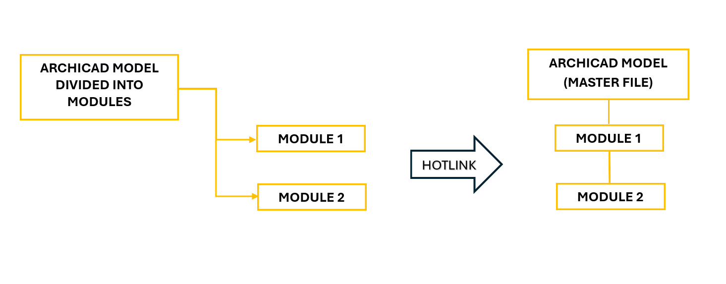
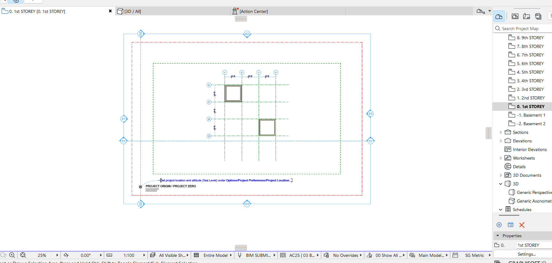
2. A sample project below where there are 2 different layouts to export into 2 different modules.
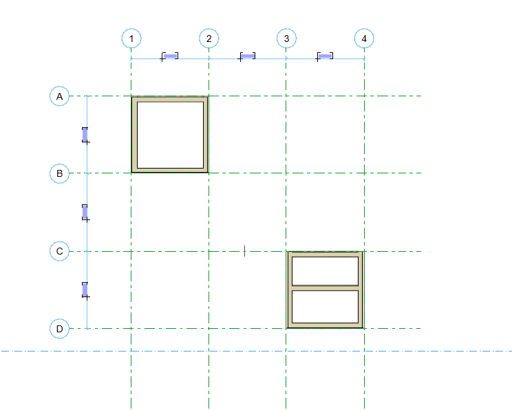
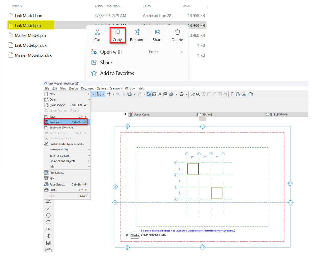
3. The layout has been saved into 2 different pln files to export as modules.
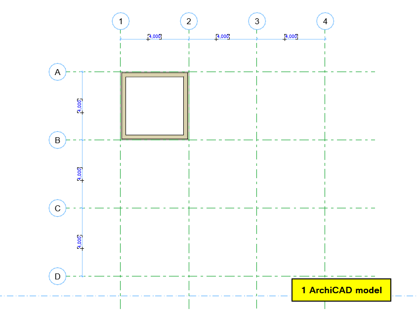
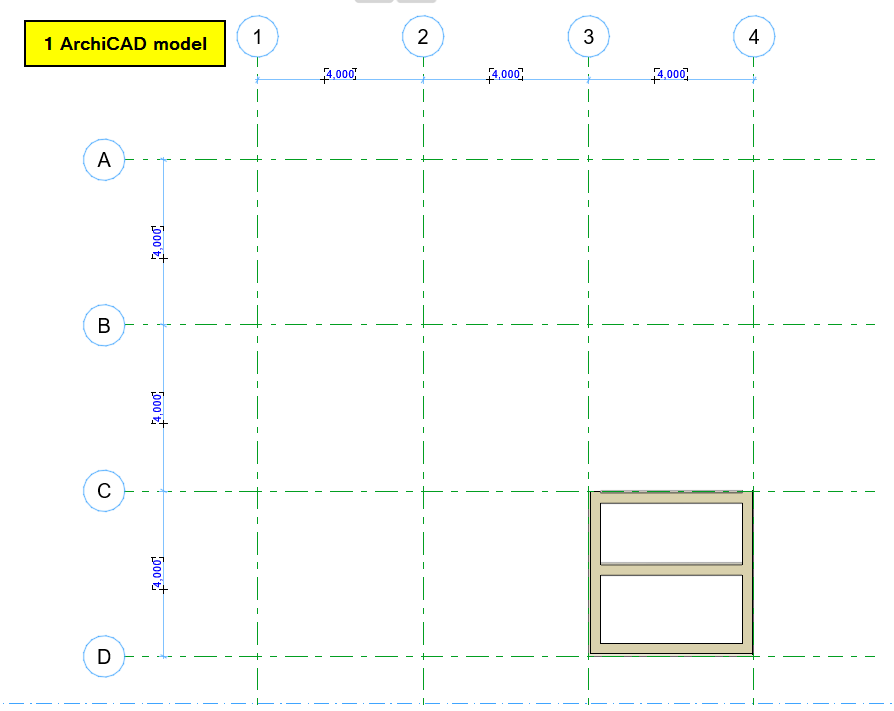
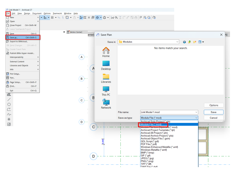
4. To export the models into modules, can simply “Save as” to desired folder and use Module File (.mod) as the file type. To repeat the process when exporting other files.
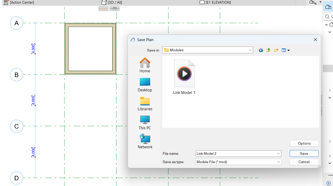
5. Now open the other ArchiCAD project (pln) for the modules to place on and follow the steps below.
File > External Content > Place Hotlink Select Module > New Module – there will be 2 options where to get the modules. Either from Local folder or from BIMCloud.
Note: Projects must have the same project origin settings
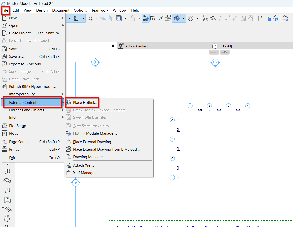
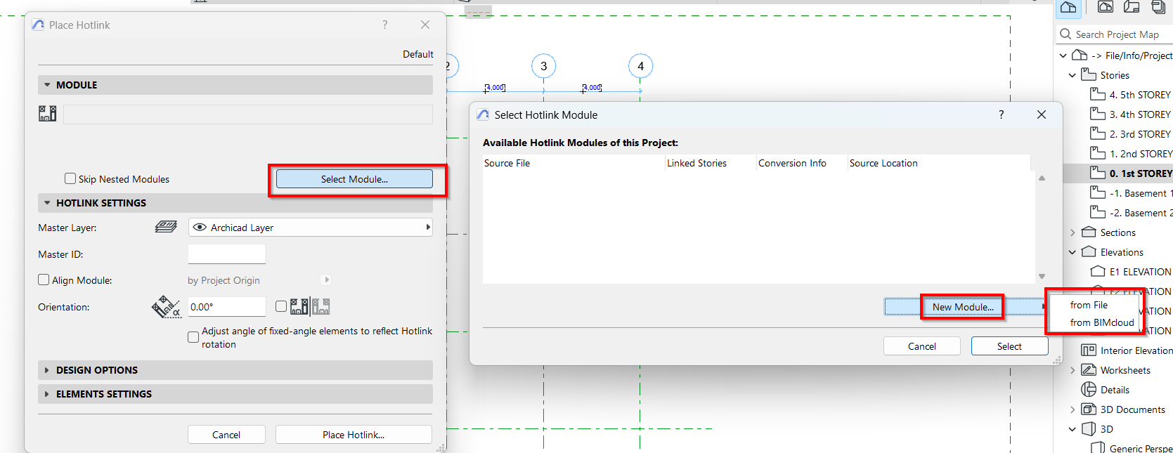
Note: To repeat the process in placing other modules.
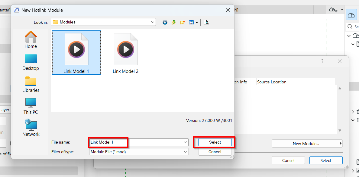
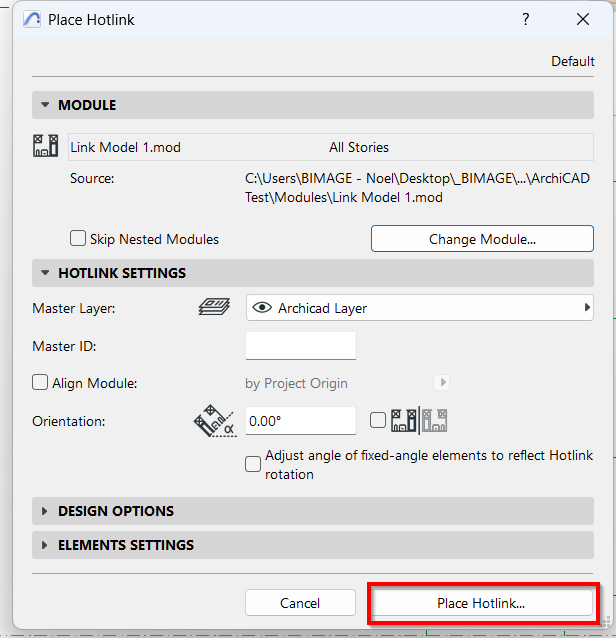
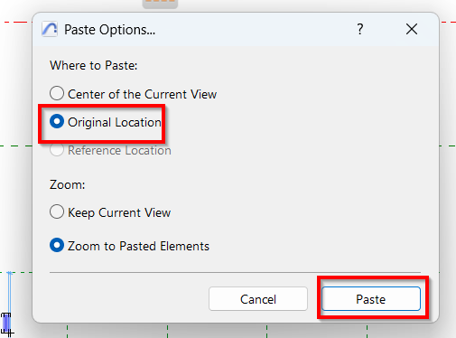
6. Once all placed, verify the model if placed in correct location.
Notes:
- Projects must have the same project origin settings
- Modules with the same/typical layout can be copied/multiplied/mirrored within the same project.
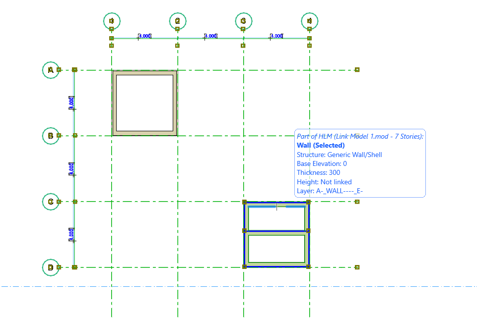
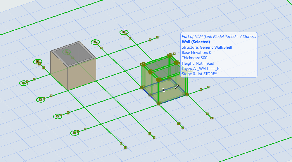
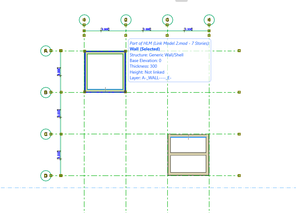
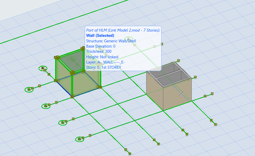
1. One option to transfer objects to another project is using the copy & paste command. This approach is applicable to AR, ST & MEPF.

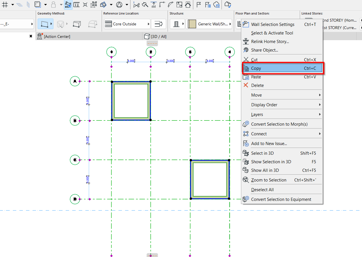
2. To begin, select the desired objects and right click > Copy (Ctrl+C) To note: Projects must have the same project origin.
3. Go to the ArchiCAD model space to paste the copied objects. Right click > Paste (Ctrl+V) To note: Projects must have the same project origin
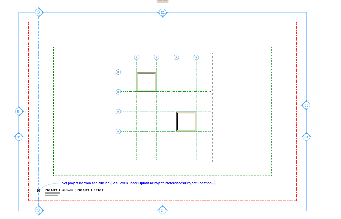
4. Now verify the copied model and properties.
1. One option for easy conversion of Archi objects to Structural (vice versa) and eliminating the time consumed on copying the objects to another project is to change the functions of the objects.
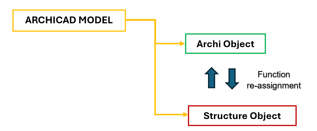
2. Using the Existing ArchiCAD project file, the user/modeler may choose to duplicate or save as the project and re-assign object parameters. For example, re-assigning wall object Function from Archi to Structural.
3. To re-assign wall function, Select the desired object and open the Settings Dialog.
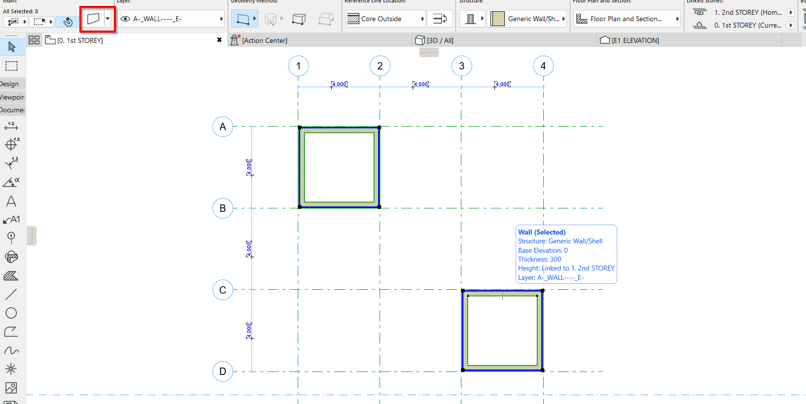
4. From the Wall Selection Setting, toggle down “Structural Analytical Parameters and change Structural Functions of the wall object.
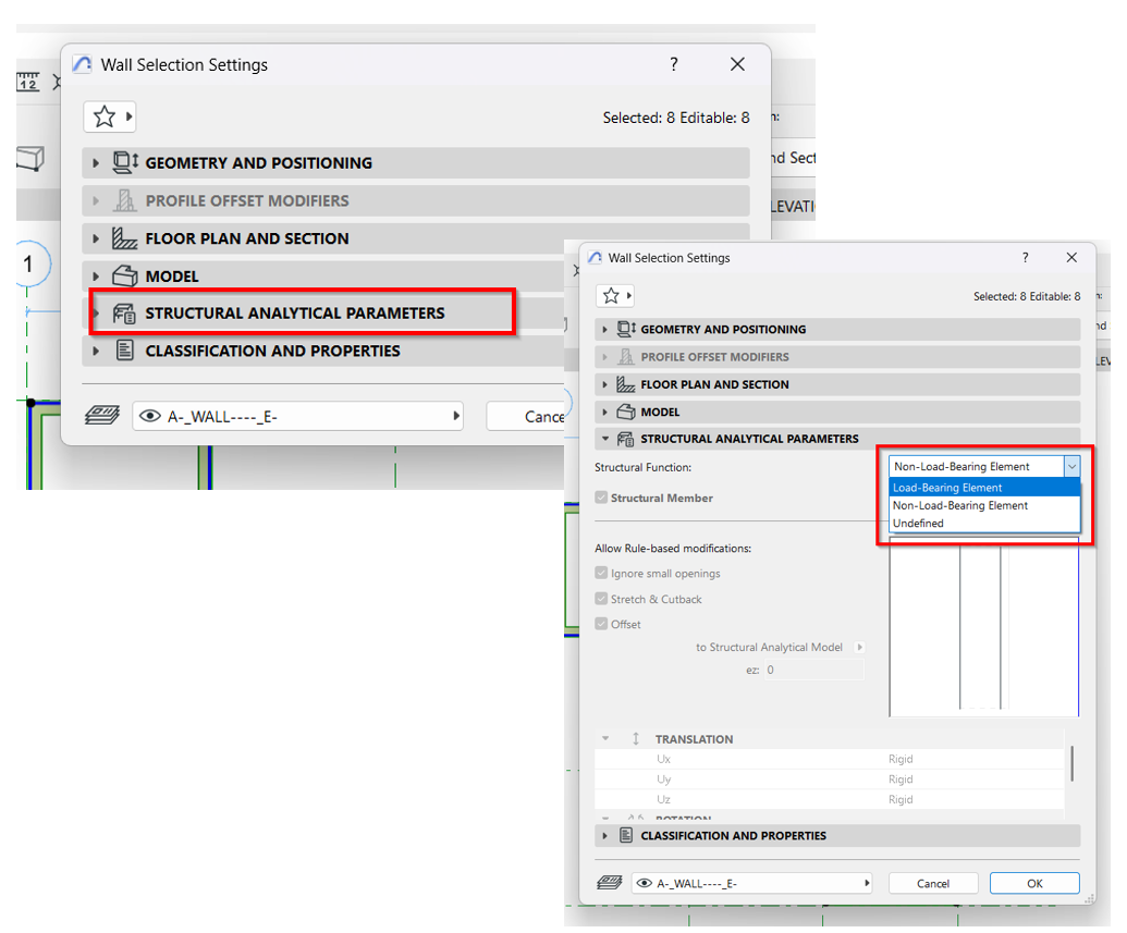
5. Once assigned, proceed to verify.
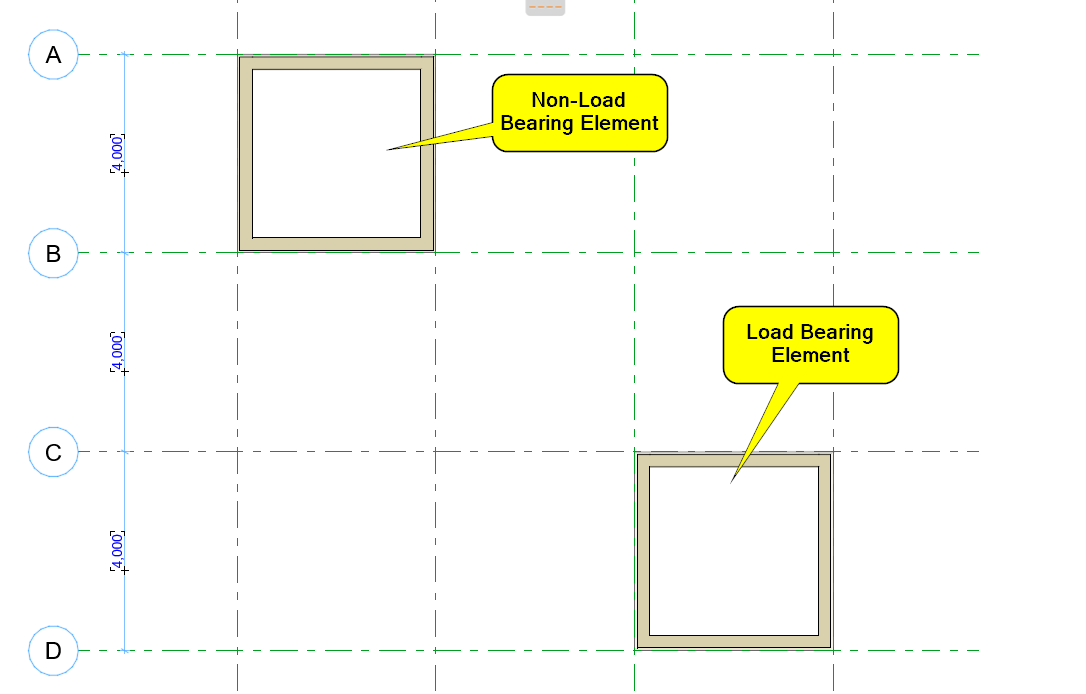
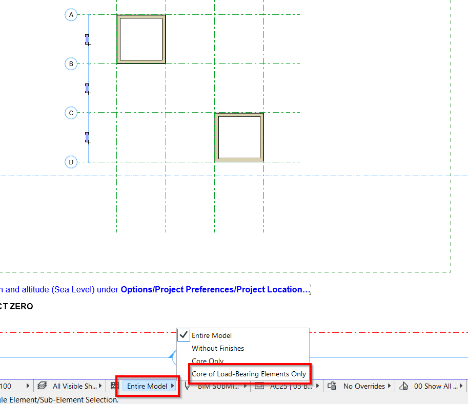
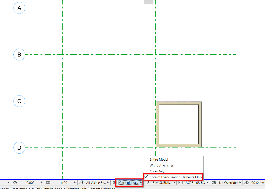
1. Copying elements from Revit linked model to current working Revit model using Copy/monitor tool.

2. Link the Revit model where elements will be copied from.
Insert > Link Revit > Position > Open
Note: to ensure linking positions used are the same in current model and Revit model to link.
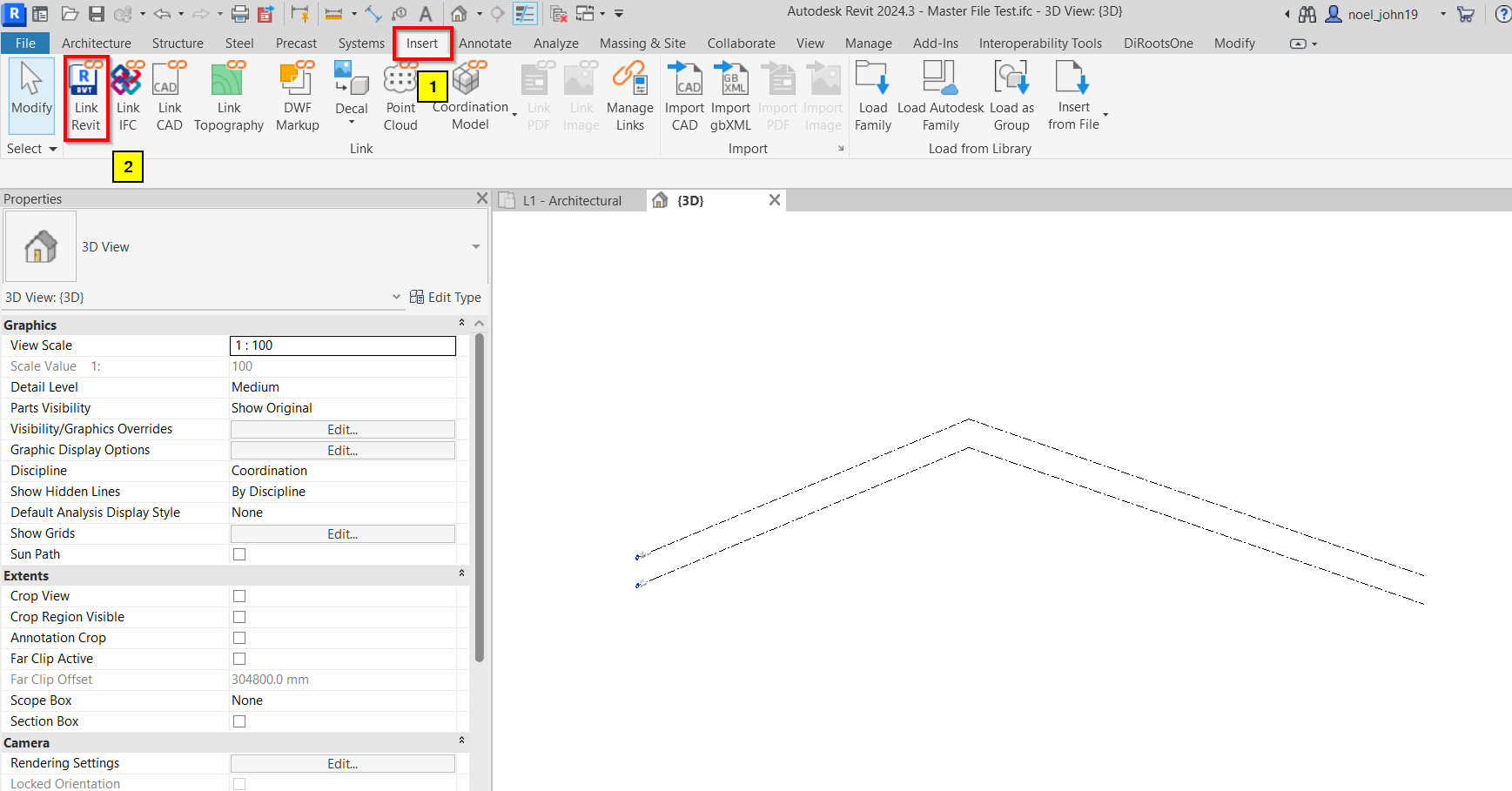
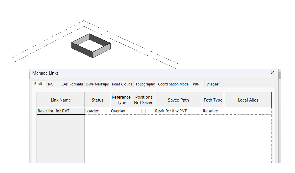
3. Once loaded correctly, modeler/user can now start the copy/monitor procedure.
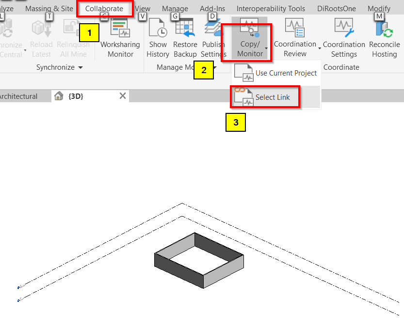
4. To begin, go to Collaborate tab and look for “Copy/Monitor” tool. Pick “Select Link” and select the linked Revit model where the elements need to copy from.
5. Once the linked Revit Model is selected, the model is now under edit mode and the user/modeler can now start copying the desired elements.
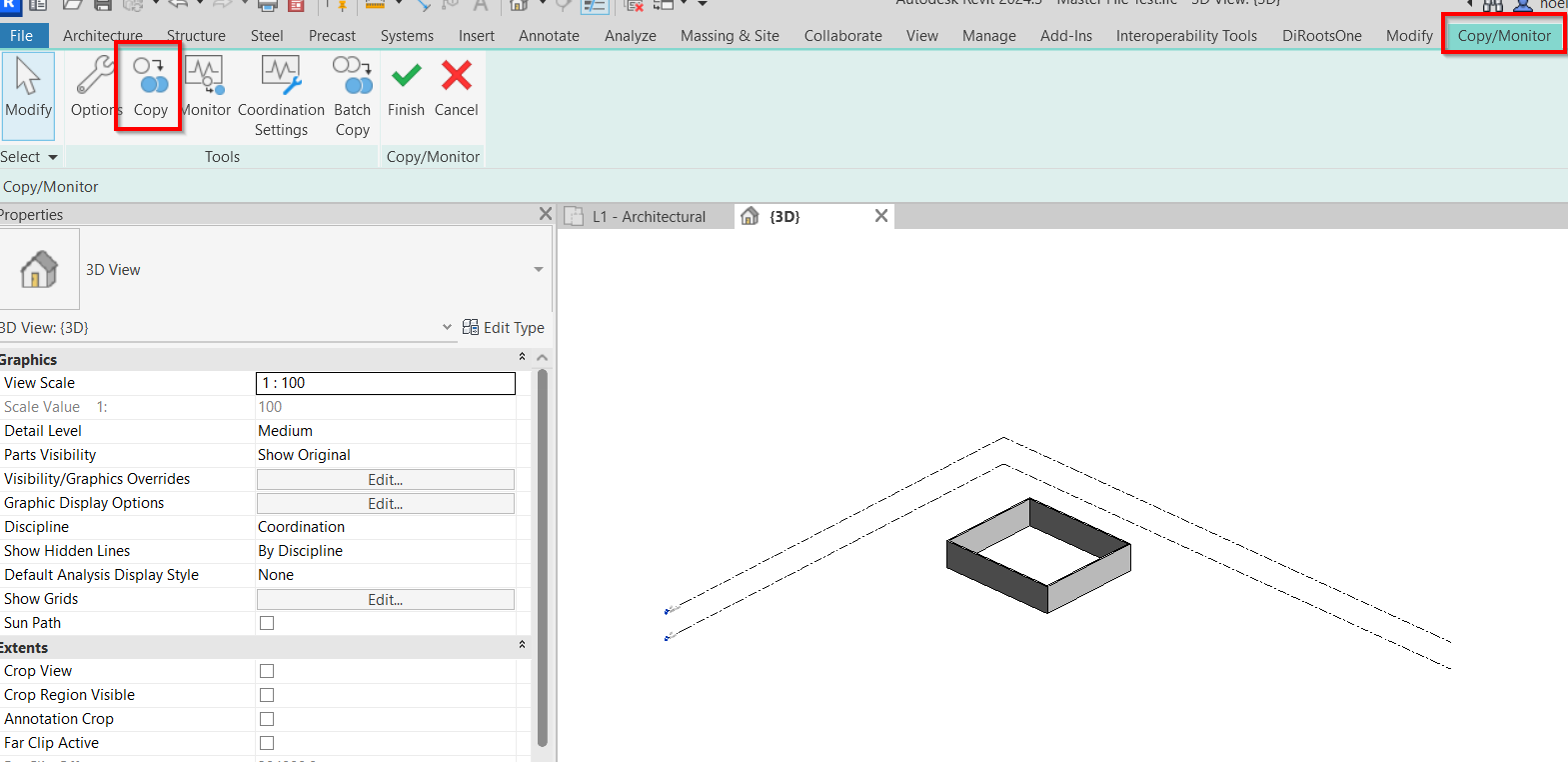
6. Uncheck “Multiple box” means copying 1 element or 1 at a time, checked “Multiple box” means selecting more than 1 elements.
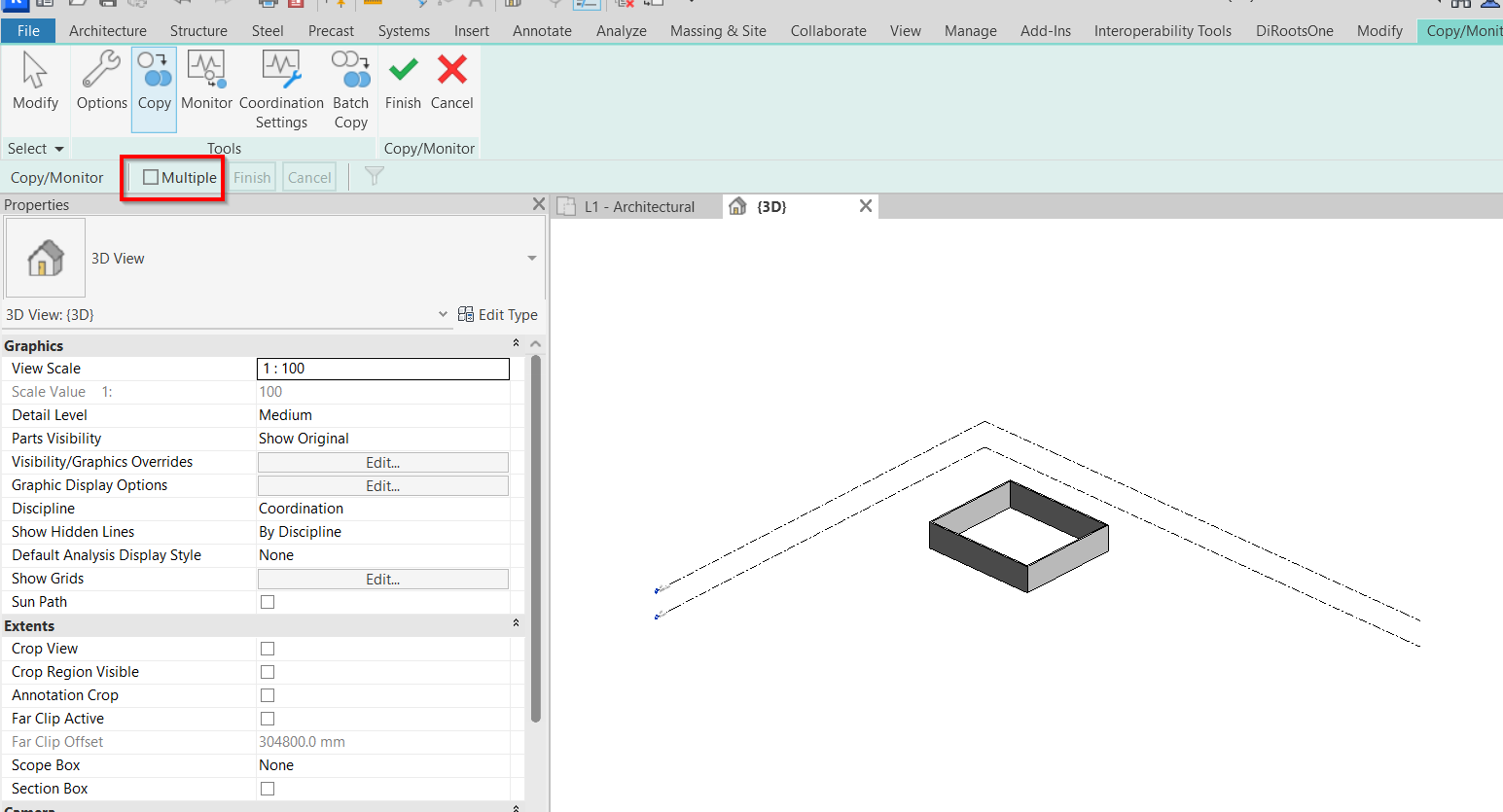
7. Once done in selection of elements, user/modeler can now click “Finish” for copying procedure and another “Finish” option for ending the edit mode.
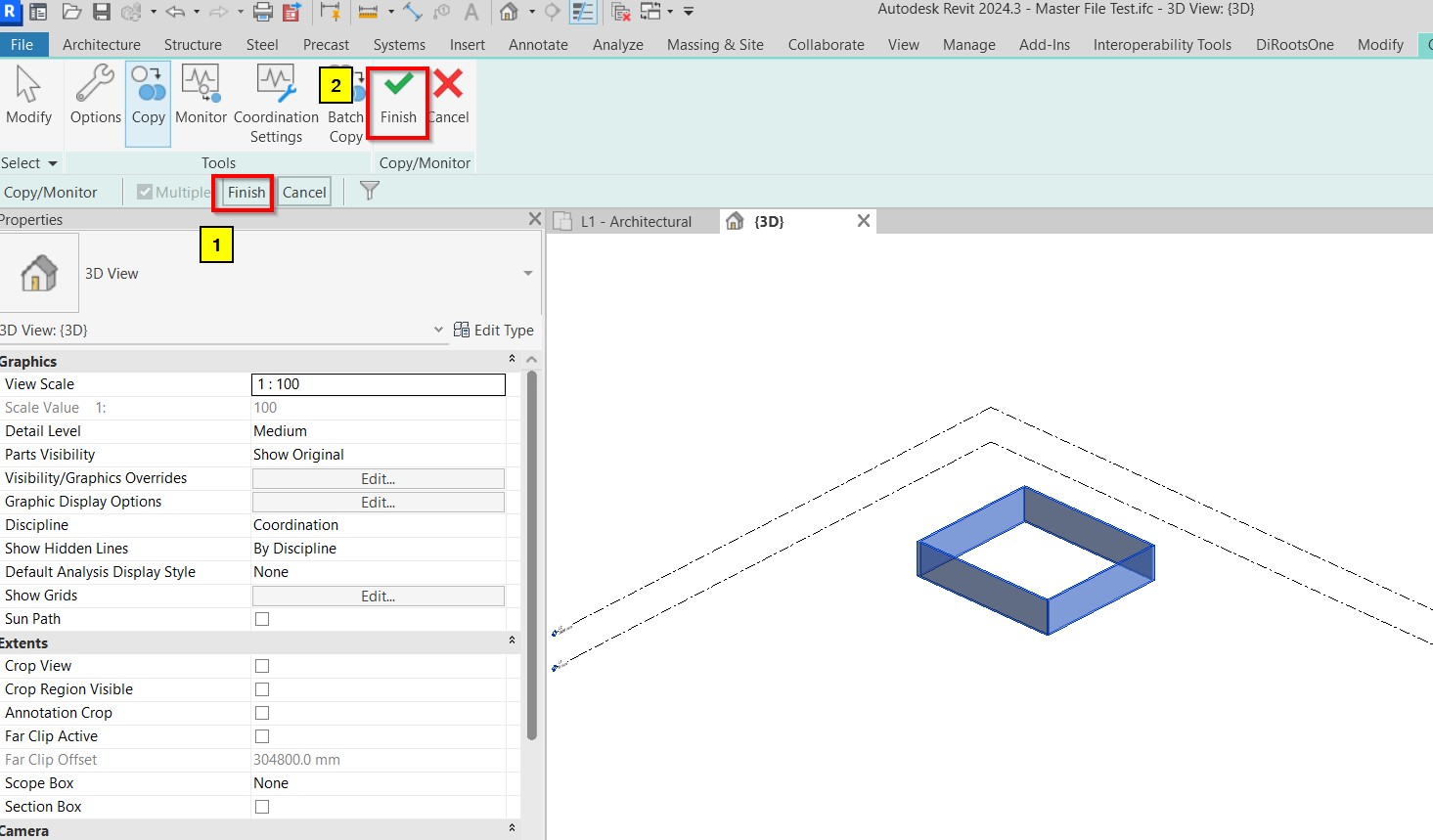
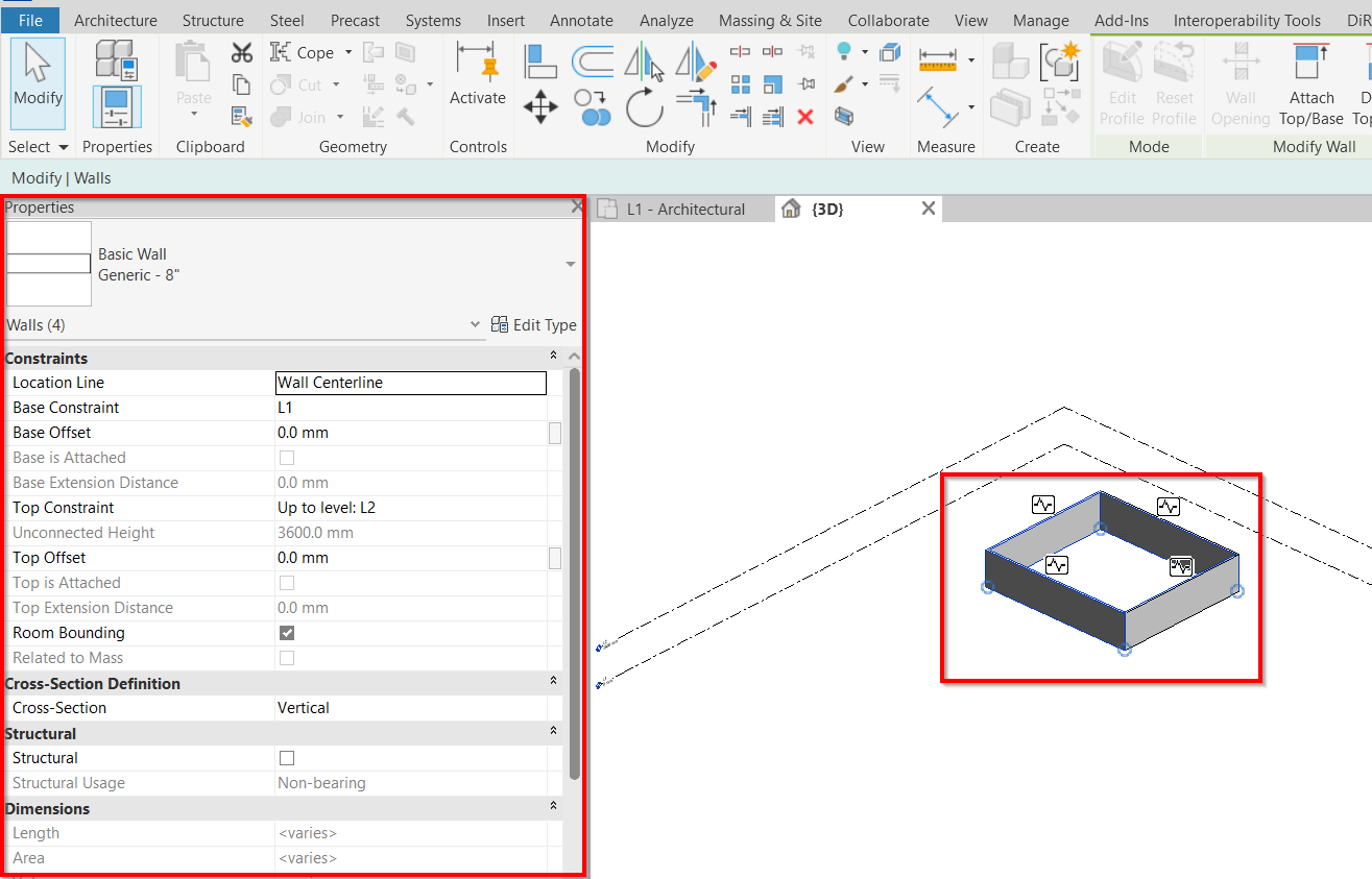
8. Elements are now copied and part of the current working model and including the properties.
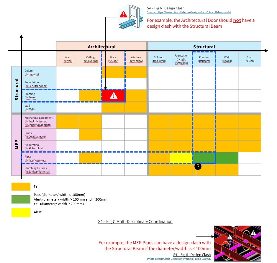
The project team should ensure that in-principle, basic / key components from each discipline do not clash with one another, as indicated in the component clashes matrix below
