Block and File Management
Besides discipline-specific models, it may be necessary to divide the project into separate parts, zones and levels for better management of the model sizes, especially for larger and more complex projects.
- Where the project involves multiple buildings, to ensure that the file size is manageable, QP should export each block as one IfcSite in a separate IFC file.
- Each block can be identified via the IfcSite “Name” attribute. Please refer here for further guidelines on how to provide IfcSite “Name” and export to IFC.
Except for linked (or hotlink) files which are repetitive modules, any linked file should not be moved in the container file (or host file) in any directions (x,y,z). The position of the linked file in relation to the project site should be set up correctly at start of the project. Any change to the position of the linked file in related to the project site should be adjusted in the linked file itself.
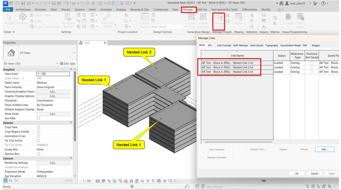
1. Architecture models are split into 4 blocks (Basement, Podium, Block A - RNL & Block B). To check the figure below for the grouping of IFC models per block.
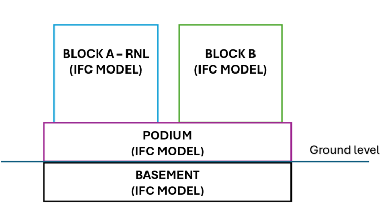
In this guide, it shows the use of a sample Block A (RNL) with nested links inside. The same procedure will be applied to each block in creating parameters to assign block names before exporting to individual IFC format.
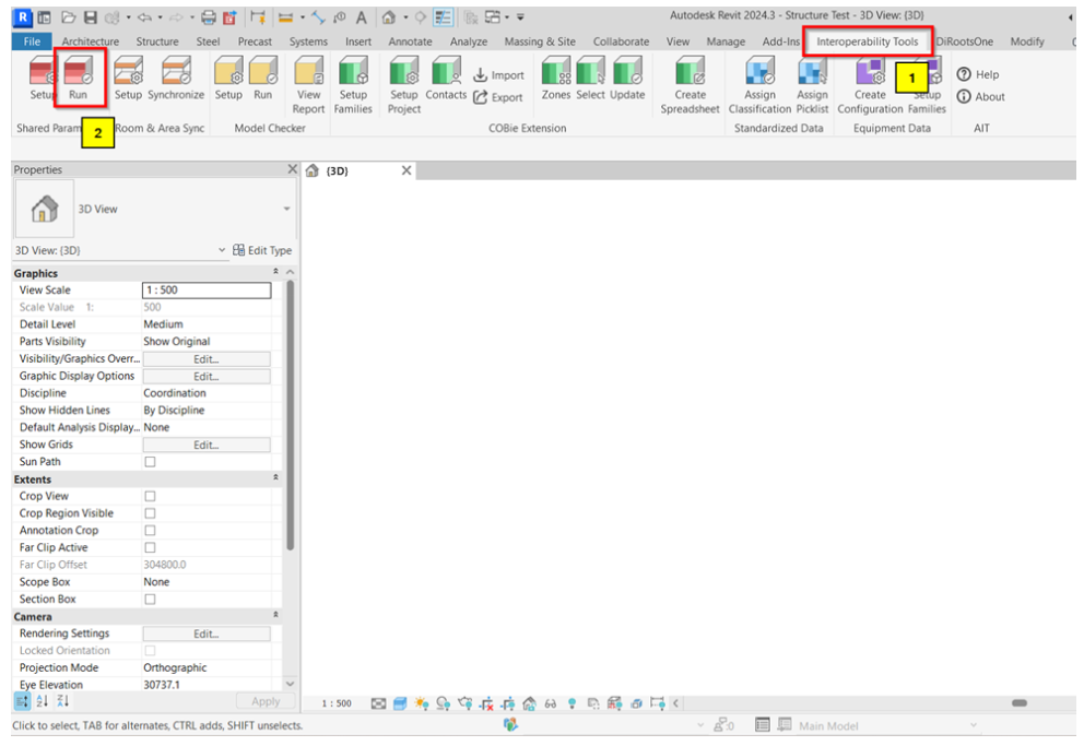
2. To begin the creation of the parameters required, always load the available parameters in ‘IFC-SG_SPTConfiguration_v2.1” using the Interoperability Tools > Run
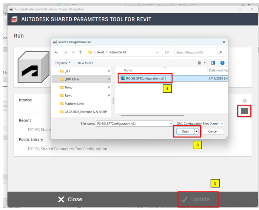
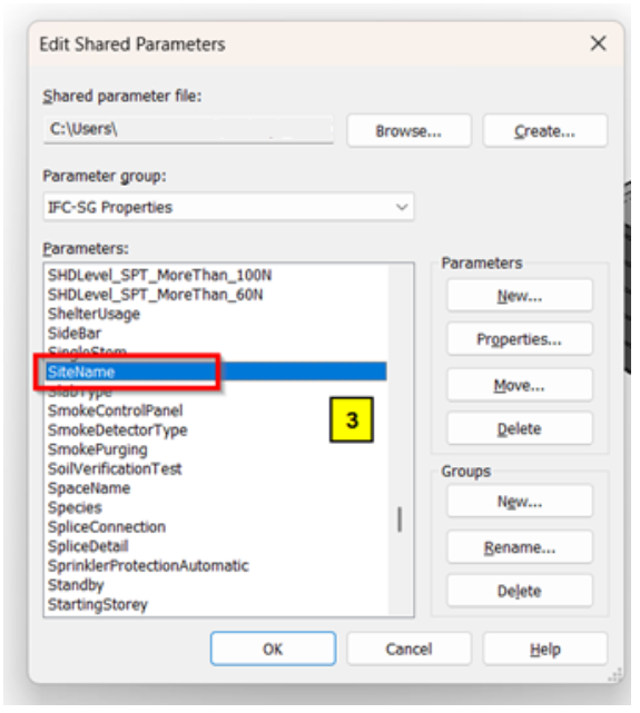
3. Blocks can be identified under SiteName.
4. Add SiteName in the Shared parameter list to be able to locate it during creation of Project parameters and adding it into the project.
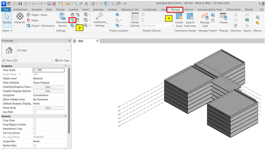
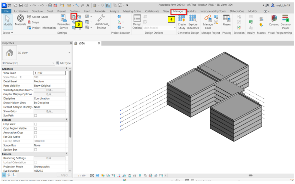
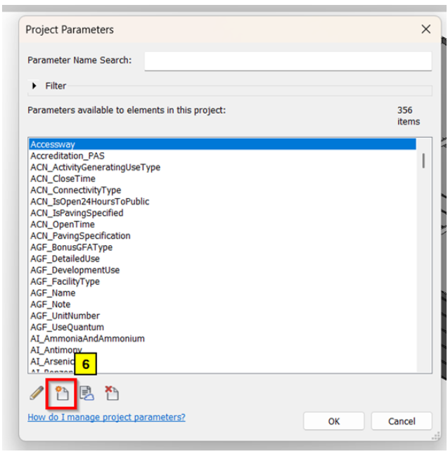
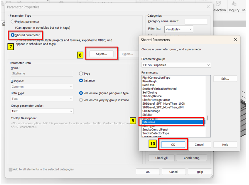
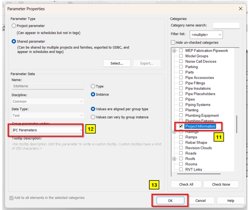
5. Assign the block names into the model under Manage tab > Project Information and look for the SiteName under IFC Parameters to input the necessary data (e.g. BLOCK A (RNL)).
6. Proceed with the IFC Export by following the sequence below.
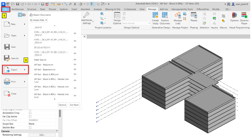
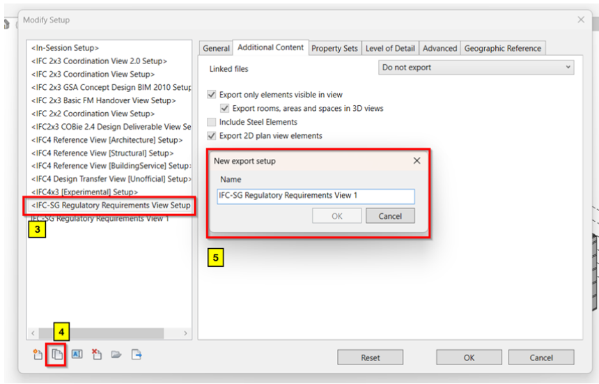
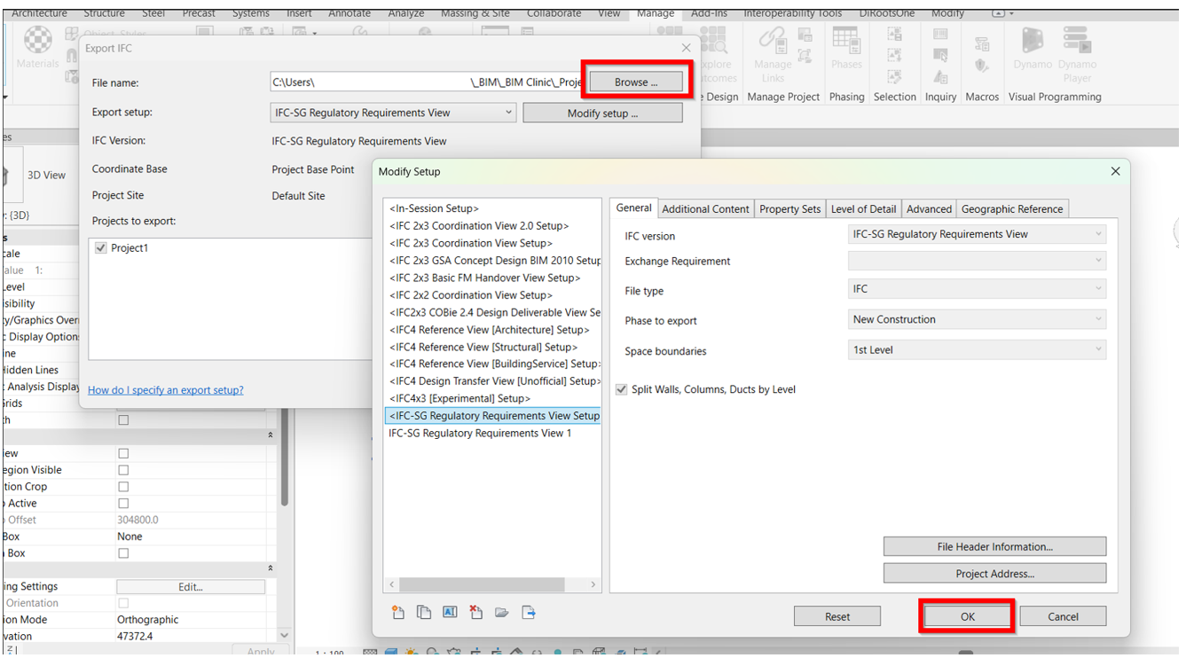
Duplicate the IFC-SG settings to be able to modify the other properties accordingly.
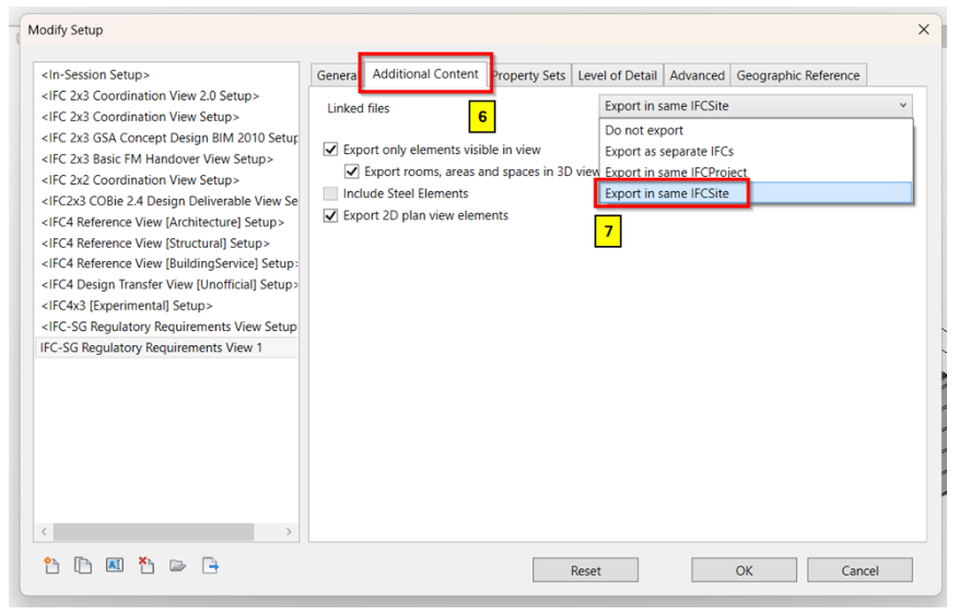
Select “Export in same IFCSite” under Additional Content tab to be able to include the link in the export.
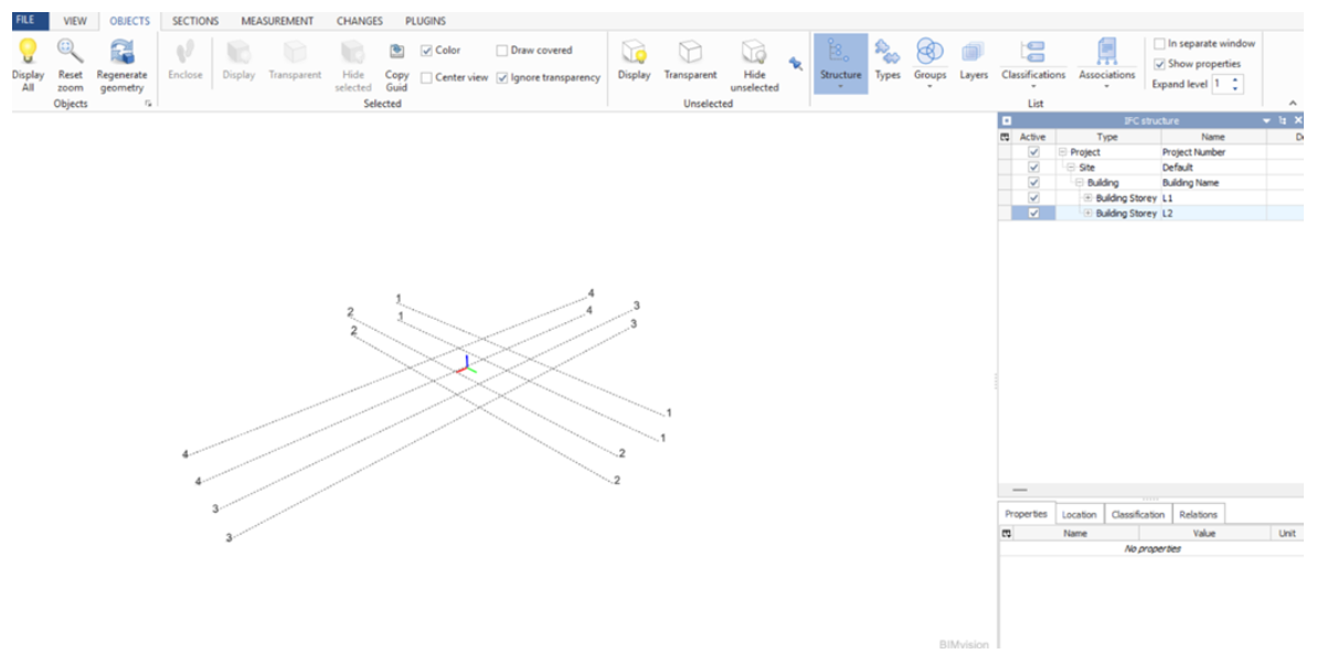
1. To ensure gridlines and levels are shown in 3D view where to do the IFC export.
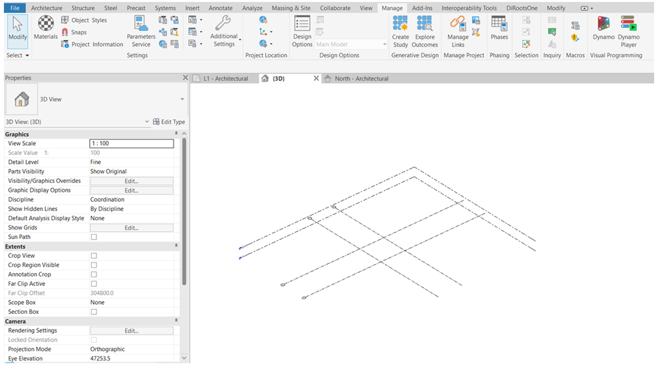
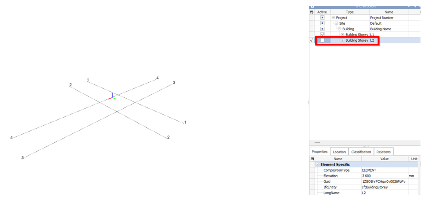
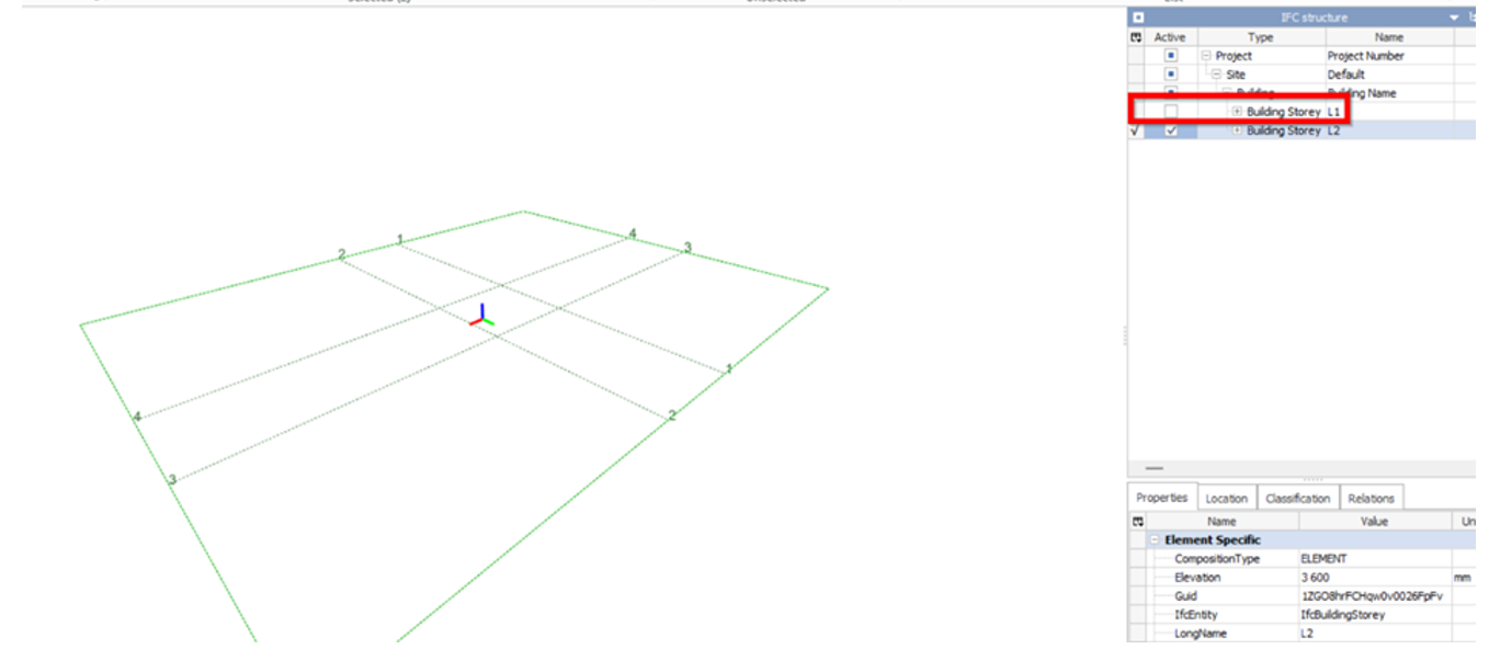
2. Since the Gridlines appearance are dependent to Levels when exported to IFC, the “Building Storey” of the levels must be enabled.
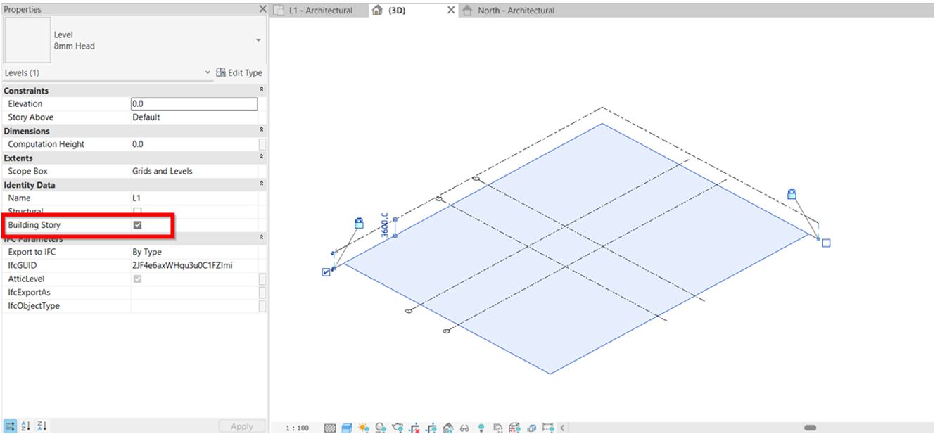
3. To Note: To show the gridlines in different levels, the user must ensure to enable the “Building Storey” of that certain level before exporting to IFC.
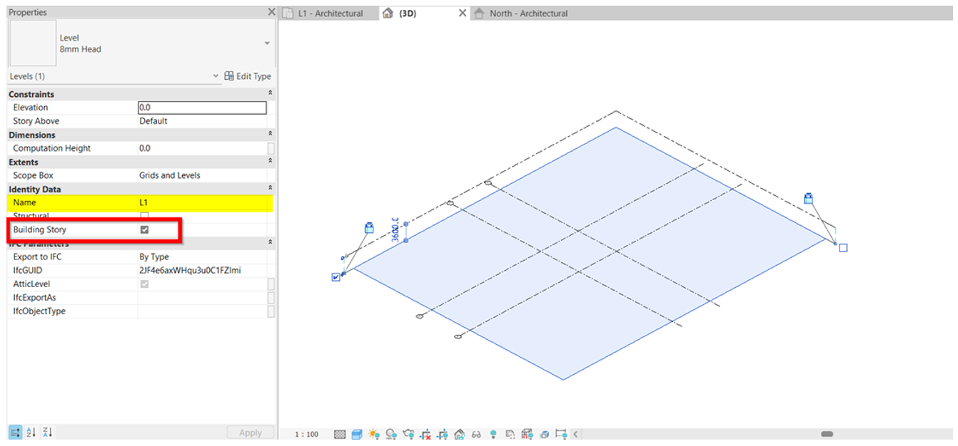
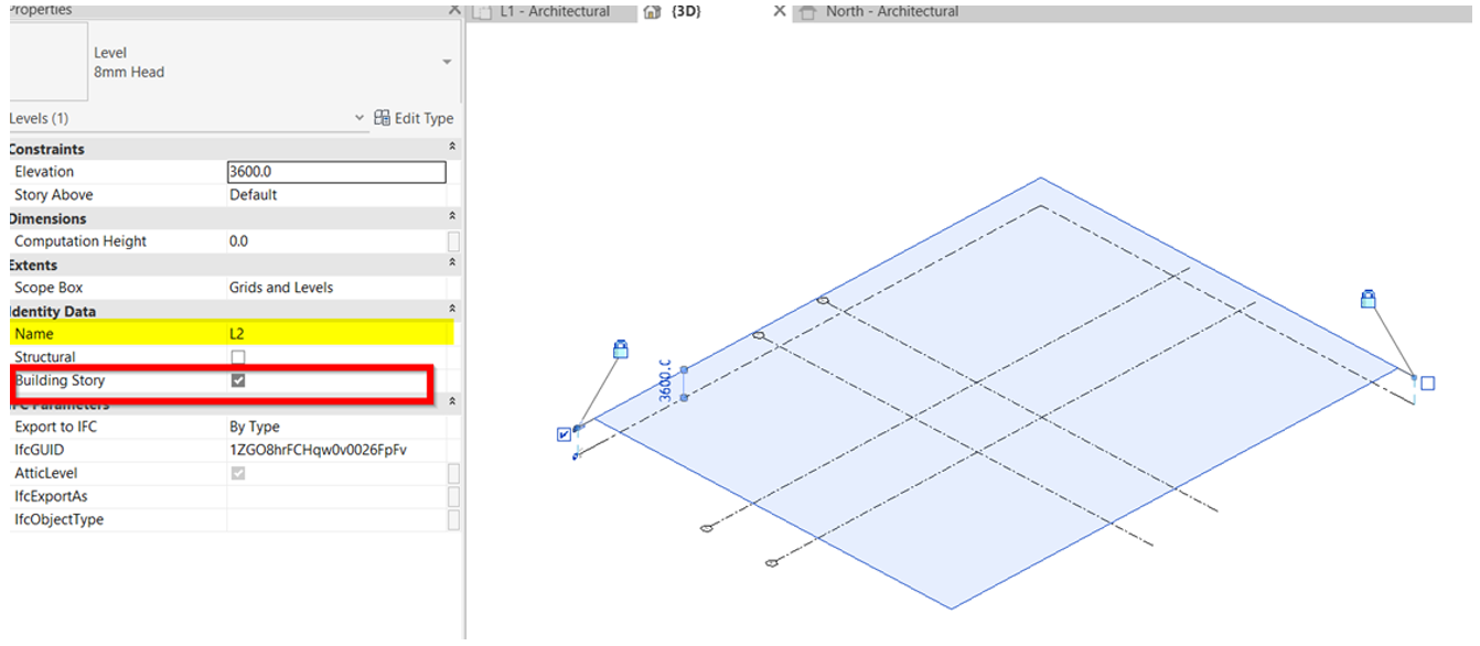
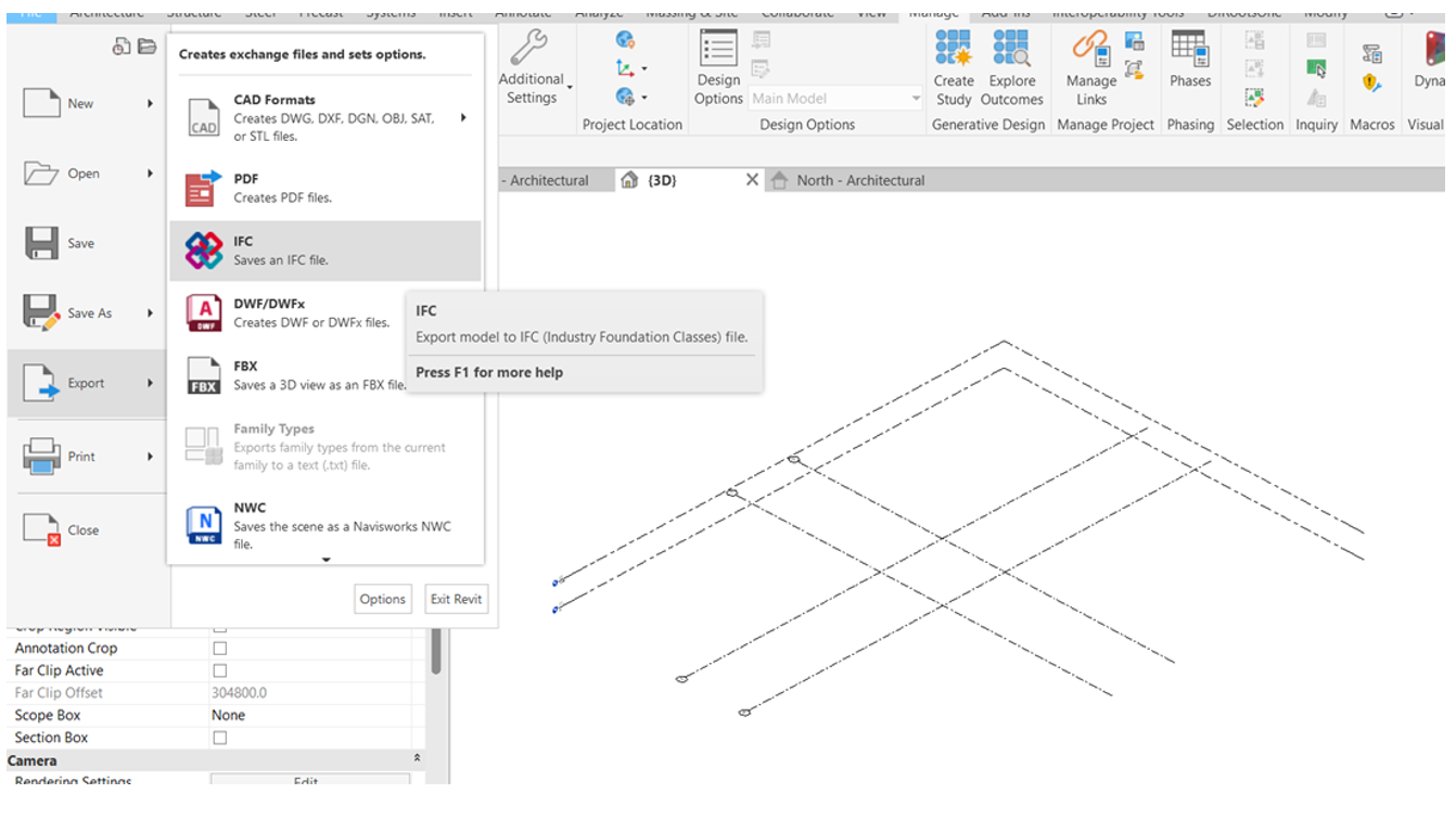
4. Once all finalized, begin with export. File > Export > IFC
5. Browse the location to save the file. No other settings required.
6. Test out the IFC exported.
