About
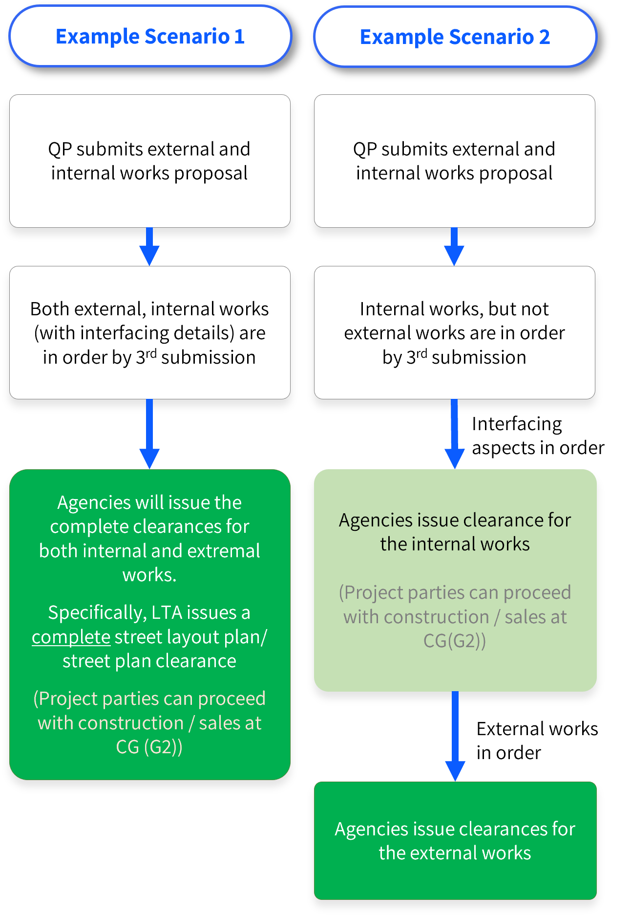
- External works of a development typically involve agencies e.g. LTA, PUB and NParks and could involve a lengthy process depending on the scope and complexity. To minimise the potential impact to the clearance of Construction Gateway, agencies will not hold back the clearance if the submission has satisfied the agencies' requirements at CG and the interfacing details between the external works and the main development are in order
- By default, the submission at Construction Gateway shall include details of the proposed external works under CORENET X. However, in a scenario where the proposed works within the development boundary, including the interfacing details are in order, and the only outstanding issues are the details of the external works, the agencies will proceed to issue the conditional clearances for internal works. QPs are required to follow up with the comments and obtain the agencies' full external works clearances

Note: The submission format for proposed works within the development boundary shall follow the prevailing BIM submission requirements. Design >proposals for external works can be submitted in 2D (CAD). Notwithstanding, agencies are open to reviewing infrastructure models prepared in 3D.
External Works
Click here for LTA External Works
Click here for NParks External Works
Click here for PUB External Works
| Agency | 2D Plan Representation / Templates | |
|---|---|---|
| Description | Examples | |
| LTA |
|  |
| NParks |
|  |
| PUB |
|  |
Note: The submission format for proposed works within the development boundary shall follow the prevailing BIM submission requirements. Design proposals for external works can be submitted in 2D (CAD). Notwithstanding, agencies are open to reviewing infrastructure models prepared in 3D.
- Under CORENET X, LTA, NParks, and PUB require:
- Proposed works within the development boundary
- Proposed external works to be submitted as a single package across the regulatory gateways to ensure that both works are well coordinated.
- For LTA:
- Works within the development boundary pertain to:
- Vehicle parking layout/Bicycle parking lots
- Layout of pick-up/drop-off (PUDO) points
- Internal driveways
- EV charging infrastructure
- External works pertain to works within the road reserve, such as:
- Street improvement works
- Commuter facilities
- Active mobility infrastructure
- Works within the development boundary pertain to:
 work - PUDO layout")

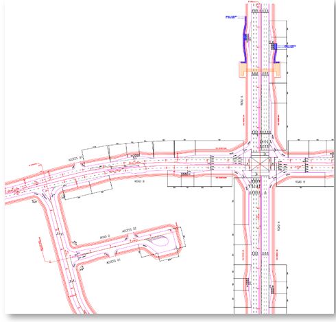
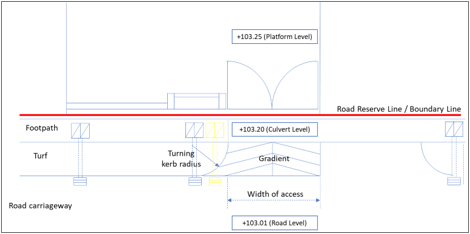
- It is common for a development to propose connections (serving various users such as motorists, pedestrians, cyclists, etc.) from within the development leading to the surrounding road network. These connections form interfaces at the development boundary. Such interfaces have to be well coordinated to ensure that the development platform level ties in properly with the existing roads. For new roads proposed in conjunction with development(s), the vertical profile of the roads (designed to comply with LTA design requirements) has to be established before other development interfacing details are considered. Additionally, interfaces usually demarcate the extent of maintenance ownership between the developer and the State.
- The layout and cross-sections of interfaces between the development boundary and the road reserve shall be clearly reflected in the external works design proposal.
| S/N | LTA and NParks Interfacing Aspects |
|---|---|
| 1 | Vehicular Access Points |
| 2 | Pedestrian Access Points |
| 3 | Cyclist Access |
| 4 | Covered Linkway/Walkway Connections |
| 5 | Pedestrian Overhead Bridge Connections |
| 6 | Pedestrian Underpass Connections |
| 7 | Bus Stops (If directly interfacing with the development building) |
| 8 | Taxi Stands (If directly interfacing with the development building) |
| 9 | Vertical Profile of New Street (If proposal involves construction of a new street or widening of existing roads) |
| S/N | PUB Interfacing Aspects |
|---|---|
| 1 | Connection of internal drain to road drain/drain outlet |
| 2 | MPL, adjacent road/ground level, and outlet discharge point levels |
| 3 | Point of proposed sewer connection |

LTA
Interfacing Aspects to be cleared as part of Development (Internal) Works
LTA considers the following as interfacing aspects:
| S/N | Interfacing Aspect | Remarks |
|---|---|---|
| 1 | Vehicular Access Points
  | Vehicular accesses have a significant impact on the development layout and have to be coordinated with the proposed Minimum Platform Level imposed.
-- |
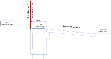
| 2 | Pedestrian Access Points
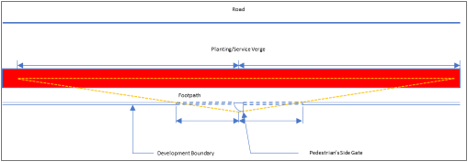 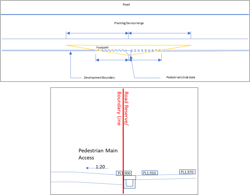 | Pedestrian accesses have to be designed with respect to the internal layout and the external amenities of interest to development users.
-- |
| 3 | Cyclist Accesses (Please refer to typical section and plan view in S/N 4) | Cyclist accesses have to be designed with respect to internal bicycle parking facilities and the surrounding road network. One of the important design issues is the provision of adequate sight distance at the development accesses and inner radius of road bends. |
| 4 | Covered Linkways (At grade connections between the development and road reserve)
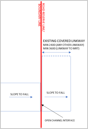 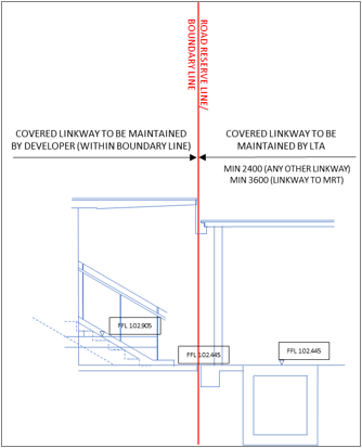 | Covered linkways have to be designed with respect to the internal layout and the external amenities of interest to development users.
-- |
| 5 | Pedestrian Overhead Bridges (POBs) (Elevated connections between the development and
road reserve)
-top-view.png?sfvrsn=5621a8b7_1) -cross-section-view.png?sfvrsn=bfbaa342_1) | Direct linkages between POBs and developments have to be designed to ensure that the levels of the POB and development can match.
-- |
| 6 | Pedestrian Underpasses (PUPs) (Subterranean connections between the development and road reserve) | Direct linkages between PUPs and developments have to be designed to ensure that the levels of the PUP and development can match. |
| 7 | Bus Stops (If directly interfacing with the development) | Interfacing (if any) between bus stops and developments have to be co-ordinated. |
| 8 | Taxi Stands (If directly interfacing with the development) | Interfacing (if any) between taxi stands and developments have to be co-ordinated. |
| 9 | Covered Walkways | Covered walkways have to be designed in relation to the open walkways for barrier-free access. |
| 10 | Vertical Profile of New Street (If the proposal involves the construction of a new street and / or widening of existing roads) | It is important to establish the vertical profile of the new street / widened street, which determines all other interfacing aspects, such as development platform levels, drainage levels, access levels, as well as the levels of any existing structures (while complying with the current design requirements). |
- LTA will issue a Layout Plan Clearance (Street & Parking) at the Design Gateway (G1), as well as a Street Plan Clearance and Vehicle Parking Building Plan Clearance at the Construction Gateway (G2), when both the proposed works within the development boundary and external works are designed in accordance with the prevailing standards.
- In a scenario where the proposed works within the development boundary are in order, whereas the external works are still under review, LTA may issue separate Layout Plan and Street Plan Approvals, for internal and external works. For LTA to issue a conditional approval, all interfacing aspects shown within the external works proposal must be designed in accordance with the prevailing standards.
- The approvals for internal works granted by LTA once the interfacing aspects have been agreed, will help to expedite the clearance and completion of the projects, notwithstanding the requirement for combined submission under CORENET X. QPs are required to follow up and obtain the agencies’ full external works clearances, before advancing to the next regulatory gateway.
Note that External Works is undergoing further refinements. More updates will be released in future COP versions.
| Key Gateways | Objective | Road alignment details to be prepared (other details to be prepared and submitted as required) | Supporting Information required |
|---|---|---|---|
| Pre-DG (Land Use, TCOT, PAFS, TIA) | To establish RRL and development boundary |
|
|
| Pre-Submission, Planning and Other Consultations | To seek clarifications for details to be submitted at DG stage | As required by Agency / QP to seek clarification from LTA |
|
| Design Gateway (G1) | To establish development platform level and development access that will properly interface with the proposed carriageway |
|
|
| Piling Gateway (G1.5) (Optional) | Piling gateway also includes earth retaining structures (slope, retaining wall, CBP etc.) within the road reserve | - | - |
| Construction Gateway (G2) | To finalise all other details necessary for construction of the road and related infrastructure works |
| - |
| Independent Submissions | To finalise individual agency requirements after construction gateway that do not have any impact on other agencies requirements | Approval to commence engineering works/restricted activities within the Railway Protection Zone | - |
* These aspects include (the necessary) interfacing works with the internal layout. Proposed interfacing works should be submitted as part of the external works design proposal and cleared in tandem with internal layout.
LTA’s External Works Requirements
Objectives:
|
|
|---|---|
|
|
|
Vehicular Access Points Connections and Interfaces at Development Boundary
|
|
|
Layout of Proposed Frontage Improvement Works
|
|
|
Design of New Street (incl. Modifications to Existing Streets)
|
|
|
Connections and Interfaces at Development Boundary
|
|
|
|
|
Layout of Covered Linkway / High Covered Linkway
Connections and Interfaces at Development Boundary
|
|
|
POB Layout
Connections and Interfaces at Development Boundary
|
|
|
Pedestrian Underpass Layout
Connections and Interfaces at Development Boundary
|
|
|
Layout of Bus Stop
Connections and Interfaces at Development Boundary
|
|
|
Layout of Taxi Shelter
Connections and Interfaces at Development Boundary
|
|
|
|
|
Cycling Path Layout
|
|
Objectives:
|
|
|---|---|
|
|
|
Vehicular Access Point Details Connections and Interfaces at Development Boundary
|
|
|
Details of External Works (Frontage Improvement Works)
|
|
|
Details of Side Table Modifications for Addition of Auxiliary Lanes, U-turns etc.
|
|
|
Details of New Street (incl. Modifications to Existing Streets)
|
|
|
Street Works Deposit
|
|
|
|
|
Detailed Architectural / Structural Layout, and M&E Provisions of Covered Linkways
Note: Refer to LTA’s Infrastructure Design Criteria, M&W Specification, Architectural Design Checklist for Covered Linkways, and M&E Checklist for a full list of requirements/detailed descriptions. |
|
|
Detailed Structural Layout, and M&E Provisions of Pedestrian Overhead Bridges
Note: Refer to LTA’s Infrastructure Design Criteria, M&W Specification, Architectural Design Checklist for Pedestrian Overhead Bridge (POB), and M&E Checklist for a full list of requirements/detailed descriptions. |
|
|
Detailed Structural Layout, and M&E Provisions of Bus Shelters
|
|
|
Detailed Layout of Taxi Shelter
|
|
NParks
Note that External Works is undergoing further refinements. More updates will be released in future COP versions.
| Key Gateways | Objective | Details to be prepared (other details to be prepared and submitted as required) | Supporting Information Required |
|---|---|---|---|
| Pre-DG (Land Use, TCOT, PAFS, TIA) |
|
|
|
| Pre-Submission, Planning and Other Consultations |
|
|
|
| Design Gateway (G1) |
|
|
|
| Piling Gateway (G1.5) (Optional) | - | - | - |
| Construction Gateway (G2) |
|
| - |
| Independent Submissions |
|
|
|
Useful Link(s):
NParks’ External Works Requirements
Objectives:
|
||
|---|---|---|
| Requirements | Supporting Documents | |
|
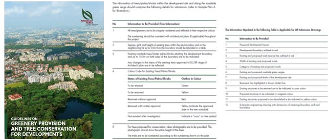
Conservation of Trees
|
Arborist report (Please refer to NParks’ Guidelines [Chapter 2]) | |
|
Green Verges
|
- | |
|
Biodiversity Impact Assessment (under URA’s Environmental Impact Assessment [EIA] framework)
|
- | |
Objectives:
|
||
|---|---|---|
| Requirements | Supporting Documents | |
|
Conservation of Trees
|
Arborist report (Please refer to NParks’ Guidelines [Chapter 2]) | |
|
Provision of Green Verges
|
- | |
|
Interfacing Aspects (from within Development Boundary)
|
- | |
|
Applicable to sites not requiring Piling Gateway (G1.5) approval Applicable to sites requiring Environmental Monitoring and Management Plan (EMMP) / Wildlife Management Plan prior to commencement of works:
|
- | |
Objectives:
|
||
|---|---|---|
| Requirements | Supporting Documents | |
|
Planting Scheme (Outside Development Boundary)
|
- | |
PUB
Note that External Works is undergoing further refinements. More updates will be released in future COP versions.
| Key Gateways | Objective | Details to be prepared (other details to be prepared and submitted as required) | Supporting Information Required |
|---|---|---|---|
| Pre-DG (Land Use, TCOT, PAFS, TIA) |
|
|
|
| Pre-Submission, Planning and Other Consultations |
| Key evaluation areas include:
|
|
| Design Gateway (G1) |
| Key evaluation areas include:
|
|
| Piling Gateway (G1.5) (Optional) |
|
|
|
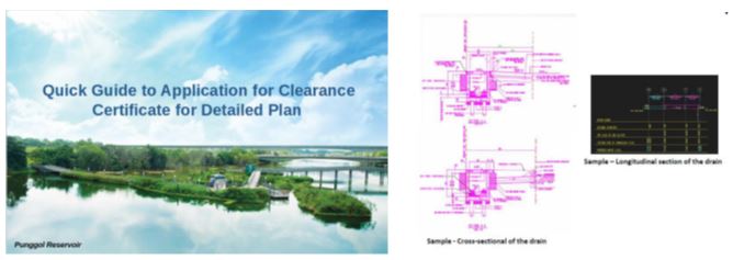
PUB’s External Works Requirements
Objectives:
|
||
|---|---|---|
| Requirements | Supporting Documents | |
|
Peak Run Off
|
- | |
|
Roadside Drain Capacity
|
- | |
|
Sewer Connection
|
- | |
|
Sewerage System
|
- | |
|
Drainage Reserve
|
- | |
| Requirements | Supporting Documents | |
|---|---|---|
|
Pre-Condition CCTV of Sewers (advisable) To be submitted via independent submission to PUB
|
- |
Objectives:
|
||
|---|---|---|
| Requirements | Supporting Documents | |
|
Public Drains (External)
|
- | |
|
Public Sewerage System (External)
|
- | |
Objectives:
|
||
|---|---|---|
| Requirements | Supporting Documents | |
|
- | |
|
- | |
|
- | |